LCC Fusion Podcast – Cards & Node Basics
A discussion of the LCC Fusion Cards including the Node Card

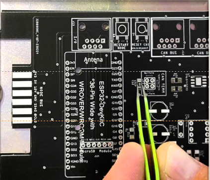
For those interested in model railroad automation, the LCC Fusion Node Card provides device control, power distribution, and network communications with other LCC-enabled devices. The Node Card’s MCU (ESP32) provides the firmware to interoperate with other LCC-compatible systems and interacts with various LCC Fusion Project devices., the LCC Fusion Node Card provides device control, power distribution, and network communications with other LCC enabled devices. The Node Card’s MCU (ESP32) provides the firmware to interoperate with other LCC compatible and interacts with the many LCC Fusion Project devices. This guide walks through the entire assembly process, following the official project documentation step-by-step. Documentation can be found here; https://patfleming.github.io/LccFusionProject/node-card-assembly-guide/
The first step in building the Node Card is to order the PCB using the provided Gerber files (link found in the Components section). These files ensure a high-quality fabrication from your preferred PCB manufacturer. Once the board is ordered, the next step is to decide on the hardware configuration.
For this build, the CAT-Wired CAN BUS Option was selected, allowing for easy communications and power connections with other NMRA compatible LCC Nodes via standard network cables. This option enables easy daisy-chaining and expands the flexibility of the system.
To simplify the build process:
Before starting assembly, it’s helpful to review the Components section in the project documentation. This provides a complete bill of materials, along with links to details about all LCC Fusion components with pricing details and ordering links under Builder’s Resources & Tips. This is especially important for ordering the correct ‘package’ size and ratings.
Use the Assembly-Configuration Options table to verify that you have all of the necessary components on hand before proceeding with assembly. Double-check that all components are correctly labeled and match the specified values to avoid errors during assembly.
With all components ready, setting up a clean workspace helps ensure a smooth assembly process:
Before applying power:
To verify CAN and I2C communication:
Once power and communication are verified:
To assist you in sourcing the necessary components for building the node card, we’ve compiled a comprehensive parts list from AliExpress.com. This table details each component, the supplier, pricing, and quantities required, providing a clear overview to streamline your assembly process.
| Product Name | Seller | Price (USD) | Quantity |
|---|---|---|---|
| ESP32-DevKitC core board ESP32 development board ESP32-WROOM-32D ESP32-WROOM-32U | WCMCU Store | $3.13 | 1 |
| 10pcs Black RJ45 8P8C Computer Internet Network PCB Jack Socket | C&S Store | $1.71 | 1 |
| 100pcs 1206 SMD Chip Multilayer Ceramic Capacitor 0.5pF - 100uF | DSSRQI Official Store | $1.41 | 1 |
| 10pcs/lot PESD1CAN TAN SOT-23 CAN bus ESD protection diode | Shenzhen IC Global Pass Co LI’s Store | $1.20 | 1 |
| 1808 125V 0451 SMD Fast Blow Fuse 0.5A - 15A | HKW Store | $2.85 | 1 |
| 10pcs/lot AMS1117-3.3V Voltage Regulator | LuLuMi Phone Store | $0.94 | 1 |
| 10pcs LM2596S Voltage Regulator Modules | Jin Tank Store | $1.84 | 1 |
| 5/10/20pcs LM7805 L7805 7805 L7812CV Voltage Regulator ICs | Moviitroni Electronic Group Store | $1.48 | 1 |
| 50pcs LM393 LM393DR LM393D SOP-8 Comparators | Supplier of Electronic Components | $1.41 | 1 |
| 10pcs SN65HVD Series CAN Transceivers | Jin Tank Store | $3.62 | 1 |
| 100Pcs SMD 1206 Resistors 0ohm - 10M Ohm 1% | CHANZON Official Store | $1.91 | 1 |
| 10PCS DIP Power Inductor 8x10mm Various Values | TLZWLA Official Store | $1.00 | 1 |
| 100PCS 1206 BLM31PG121SN1L 120 OHM SMD Chip EMI Ferrite Bead | C&G Semiconductor | $2.73 | 1 |
| Resettable Fuse 30V PTC Polymer PPTC DIP JK30 0.5A - 10A | DQLZV Official Store | $1.89 | 1 |
| 100pcs SOD-123 1206 SMD Zener Diode 2V - 47V | JINLU Store | $1.28 | 1 |
| 100PCS TVS Diode SMBJ Series 16A - 33A SMD | Good Good Cheap Electronics Wholesale Store | $4.76 | 1 |
| 10pcs SMD Polymer Solid Capacitor 6.3V - 1000uF | Auwah Store | $1.94 | 1 |
| 10pcs DIP Solid Electrolytic Capacitor Super Low ESR 6.3V - 1000uF | HKW Store | $2.97 | 1 |
| 10PCS A B C D Case Tantalum Capacitor 6V - 50V 0.1uF - 330uF | FXI Electronics Co., Ltd. | $1.32 | 1 |
The LCC Fusion Node Card is a versatile addition to any model railroad automation project, providing interoperability with other LCC Nodes in your network and communicating with LCC Fusion cards for automation. By following the documented process, assembling the board becomes an **accessible and repeatable task.
✅ Ordering a stencil with the PCB ensures quick and accurate paste application. ✅ Printing the color-coded assembly diagram simplifies component placement. ✅ Using the provided tables ensures correct component orientation. ✅ Verifying continuity before power-up helps prevent damage. ✅ Testing CAN/I2C communication ensures seamless integration with other LCC nodes.
For those planning their own build, the documentation provides everything needed to get started.
A discussion of the LCC Fusion Cards including the Node Card
A detailed walkthrough for assembling the LCC Fusion Node Card, from ordering the PCB to verifying the final build.
As the creator of the LCC Fusion Project, I built this documentation to help model railroaders and DIYers explore LCC automation—even if they’re new to elect...
Explore the LCC Fusion Project and discover how it’s transforming model railroad automation with modular design and ESP32 technology. Dive into the documenta...
Discover the LCC Fusion Project’s breakthrough in model railroading, where advanced LCC technology brings train stations to life. From detection to precise c...
Dive into the world of Layout Command Control (LCC) and learn how this innovative technology is revolutionizing model railroading. From basics to benefits, g...
Unlock the full potential of your model railroad with our step-by-step guide on crafting custom cables for effortless layout automation. Discover the secrets...
Step into the world of custom PCB design tailored for model railroads. Our comprehensive guide on using Fritzing demystifies the process, empowering you to b...