LCC Fusion Podcast – Cards & Node Basics
A discussion of the LCC Fusion Cards including the Node Card

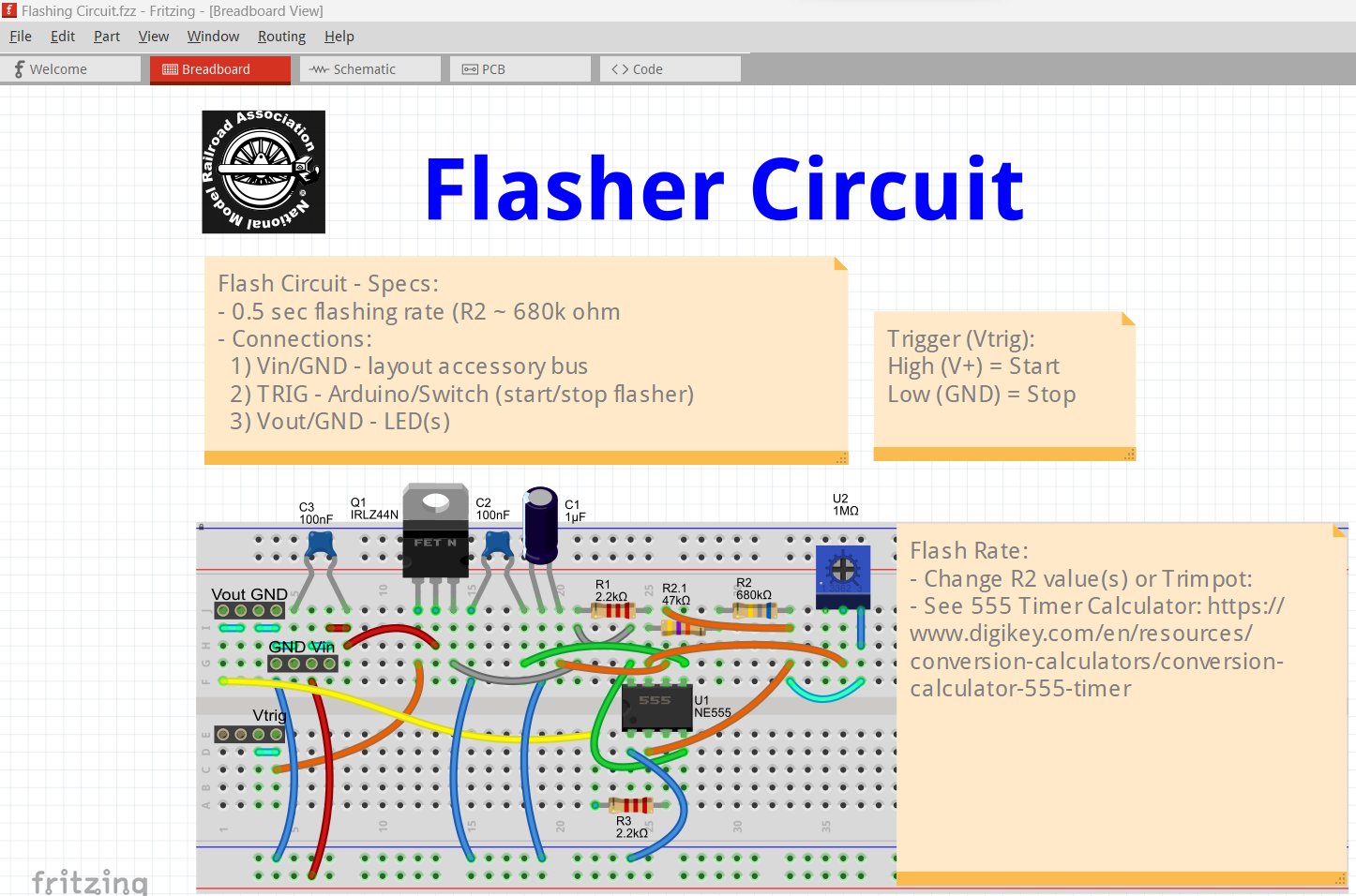
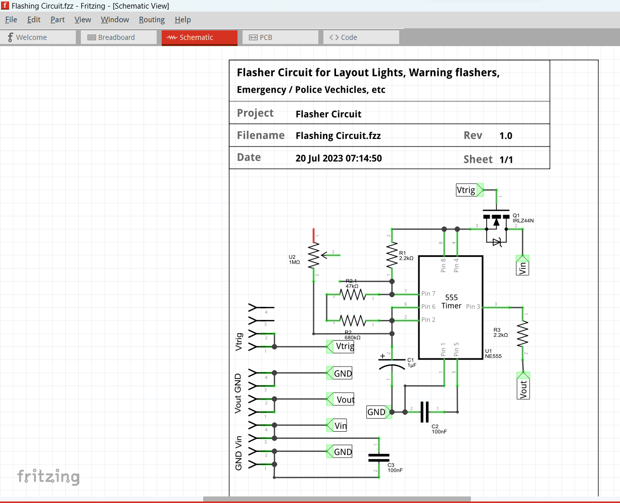

Creating printed circuit boards (PCBs) can be both fun and useful in automation model railroad layouts. Fritzing is a powerful open-source tool that simplifies the process of designing and creating these PCBs for hobbyists. During the NMRA 2023 Texas Express convention I did a 2 hour presentation on using Fritzing to create a timing circuit. The presentation covers all aspects of a timing circuit, from creating schematics, breadboards and actual PCB designs. It finishes with how to actually order a working PCB for a timing circuit.
Even though I’ve used Fritzing for the last 3 years to create a large number of circuit boards for my NMRA LCC projects, I still learned a lot in doing the presentation. Hopefully you’ll get a chance to use the presentation to get started on a PCB for your layout.
So, why did I choose Fritzing vs other PCB fabrication tools?
Fritzing is user-friendly and allows for quick prototyping with a wide range of components at your disposal. Here are some reasons why it’s a great choice:
Fritzing is a tool for designing PCBs, which are like the brains of electronics. It’s affordable and powerful. Here’s what I’ve discovered using Fritzing for my projects that involve creating PCBs for automated controls:
Affordable PCBs: There are companies like JLCPCB that make high-quality PCBs for less than a dollar. They’ve even started offering fast shipping for a low price.
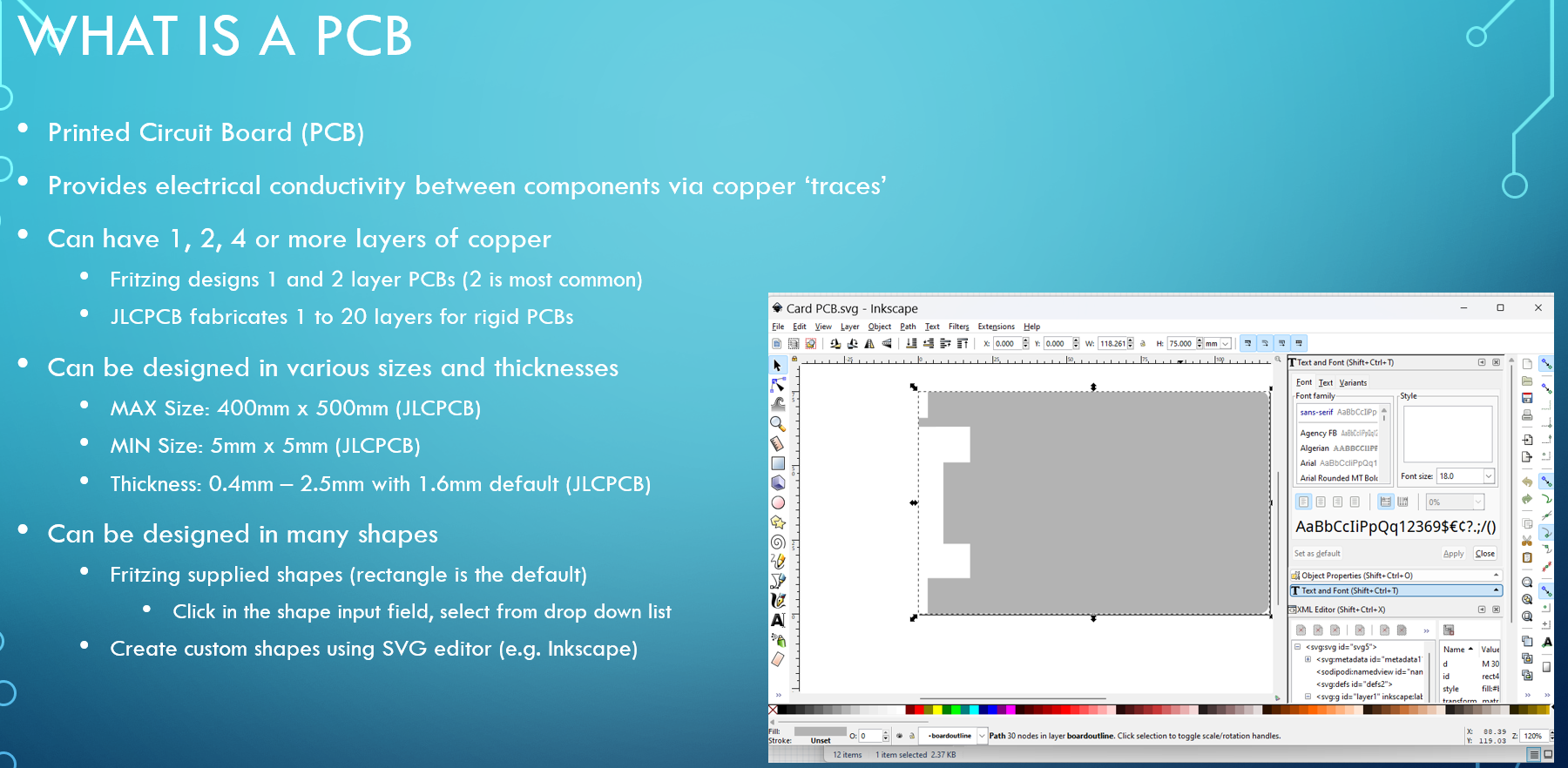
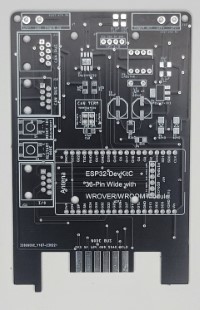
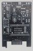 Custom PCB Shapes: For my specific layout automation needs, for the LCC Node and I/O boards, I made unique-shaped PCBs that fit into card edge connectors in only one direction to prevent costly mistakes from electrical shorts. To create the custom PCB shape, I used a program called Inkscape to draw the shape and then imported it into Fritzing.
Specialized PCB - after learning the basics of creating PCBs, I realized it might be more user friendly when implementing LCC automation to have specialized boards. For example, one PCB used as an LCC Node, and different PCBs for each of the I/O types (button, RFID, signals, voice, sound, etc). This prevents overloading a single board with too many capabilities, which leads to confusion during configuration.
Creation and modification of ‘parts’ - when working with some of the existing parts, I found it necessary to use the Fritzing Parts Editor to either change the part’s silkscreen text or to tweak the copper pads. Since I found it to be a tedious process, I only did it when necessary, but was rewarded with a better part design.
Custom PCB silkscreen - I found it useful to standardize the silkscreens for both the top and bottom of the PCBs. I used Inkscape, to update the silkscreen layers for the PCB image (SVG file) that can then be loaded into Fritzing.
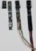
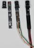 Small PCBs for Signal Heads and Masts - With Fritzing, I could make really thin PCBs, perfect for signal mast and also for inserting into the back of commercial signal heads. The PCBs were cheap and could be customized for different types of LEDs for the lamps. Plus, they made wiring really easy. The signal mast were also designed to have attached wires or insert into a socket (to allow for quick removal).
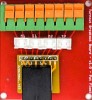
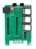
Custom boards for wiring - I found that are many types of wiring techniques used in layouts; plugs (JST, Molex, RJ45), PCB pads or holes, and terminal connectors (screw, spring). To accommodate mixing these techniques, I created small PCBs to allow for connections between different connector types. For example, an RJ45 connector (CAT5 / CAT6 cables) connection to a spring terminal with (8) connections.
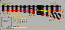
LCC Testing PCB - after mastering customer PCB shapes, silkscreen, and NMRA sessions on testing LCC hardware, I decided to create a board that supports testing signaling with a turnout and blocks. Setup is done by inserting 2(2) I/O PCBs, (5) signal mast PCBs, a Tortoise Switch Machine(TM) (inserted into a custom PCB). Note that the PCB provides solder pads for mounting the turnout rails. The rails are isolation into (4) blocks and connected via PCB traces to a socket connector for a single custom Block Occupancy Board (BOD). There is also a connector for the Signal Heads board, which is connected via PCB traces to (6) signal mast PCB socket connectors. The I/O boards are CAT6 cabled to a custom Node PCB. Both layout and accessory terminal connections provide power via PCB traces to the rails and the appropriate BOD and Turnout, and signal masts PCBs.
Remember, the presentation will cover all of these points in more detail.
In the presentation, the following topics are covered in detail:
In addition to the presentation (ppt, pdf, zip and mp4 formats), I’ve also provided:
Designing PCBs with Fritzing can be a rewarding experience. I hope this guide helps you bring your electronic projects to life. For more details, check out my full presentation attached below.
A discussion of the LCC Fusion Cards including the Node Card
A detailed walkthrough for assembling the LCC Fusion Node Card, from ordering the PCB to verifying the final build.
As the creator of the LCC Fusion Project, I built this documentation to help model railroaders and DIYers explore LCC automation—even if they’re new to elect...
Explore the LCC Fusion Project and discover how it’s transforming model railroad automation with modular design and ESP32 technology. Dive into the documenta...
Discover the LCC Fusion Project’s breakthrough in model railroading, where advanced LCC technology brings train stations to life. From detection to precise c...
Dive into the world of Layout Command Control (LCC) and learn how this innovative technology is revolutionizing model railroading. From basics to benefits, g...
Unlock the full potential of your model railroad with our step-by-step guide on crafting custom cables for effortless layout automation. Discover the secrets...
Step into the world of custom PCB design tailored for model railroads. Our comprehensive guide on using Fritzing demystifies the process, empowering you to b...