LCC Fusion Podcast – Installation Example: Detection, Signals & Turnouts
In this LCC Fusion podcast episode, Nelson and Harrison walk through a complete installation example using three core Fusion devices:
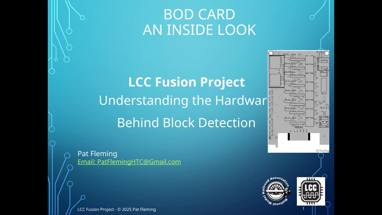
- a BOD Card and Breakout Board for block detection
- a Signal PWM Card and Signal Breakout Board for mast control
- a Turnout Card and Breakout Board for a stall-motor switch machine
These devices all connect through the Node Card, which handles the CDI configuration, logic, and CAN communication.
This episode focuses on how these pieces fit together in a simple, realistic, step-by-step install.
Watch the Podcast
AI-Assisted Production Notice
This podcast uses AI-generated voices based on the author's guidance, notes, and technical material. The goal is to present the information clearly and consistently, and to keep it easy to update as the LCC Fusion Project evolves.
All technical content, explanations, and project decisions are human-authored.
What this episode covers
🚆 A Simple Three-Device Installation
Nelson and Harrison begin with a straightforward setup:
one detected block, one signal mast, and one turnout.
Each device uses its own Fusion card and its own breakout board, all powered and connected through the Node Card and Hub.
The goal is to demonstrate how quickly a Fusion installation comes together without soldering complex control panels or writing any firmware.
⚙️ How the Cards Connect
The episode highlights how:
- The Node Card supplies power, CAN, and I²C
- Each card plugs directly into the Node Bus Hub
- Each breakout board mounts under the layout, close to the device it serves
- Standard network cables connect cards to breakouts
- Wiring stays clean, modular, and predictable
Nelson wonders how much wiring is needed.
Harrison explains how breakouts keep the wiring extremely short, making installation neat and reliable.
🛠️ Basic CDI Configuration
Most CDI fields use safe defaults, and the Node Card automatically identifies connected cards.
Only a few settings typically need changing — like device labels or addresses.
Simple control, such as a button turning a device on or off, requires no logic, since CDI can map these actions directly.
🧠 When Logic Is Needed
Logic comes into play when conditions matter.
Signals are the perfect example.
In the episode, the Node Card is configured so that:
- when the block becomes occupied, the mast changes to STOP
- when the block becomes clear, the mast returns to CLEAR
All logic lives only in the Node Card.
The BOD Card and PWM Card simply report their data and respond to events — they never run logic themselves.
🔁 End-to-End Example
The podcast walks through the complete flow:
- The BOD Breakout senses current in the block
- The BOD Card reports the reading
- The Node Card interprets it as “occupied” or “clear”
- CDI logic updates the signal aspect
- The Signal Breakout Board drives the LEDs on the mast
Nelson captures it perfectly:
“Block → Node → Logic → Signal.”
📈 Scaling the Hardware
Growing the system is simple:
- Add more BOD Cards for more blocks
- Add more PWM Cards for more signals
- Add more Turnout Cards for more switch machines
The installation pattern never changes—
cards plug into the Hub, breakouts mount near the device, and wiring stays short.
🧩 When Logic Becomes More Sophisticated
The episode lightly touches on cases where logic becomes richer, such as:
- distant signals that depend on more than one block
- aspects that depend on turnout alignment
- simple interlocking conditions
Even in these cases, rules remain readable and manageable.
Fusion grows horizontally, not in difficulty.
🎬 Bringing It All Together
To finish the example, the episode summarizes the entire cycle:
- Install the cards into the Hub
- Mount the breakout boards under the layout
- Open the CDI and accept most defaults
- Add a couple of easy logic lines
- Start operating immediately
No coding.
Minimal wiring.
Clean, modular behavior.
Why This Installation Method Works So Well
Fusion’s installation model centers around:
- consistent card form factors
- breakout boards that reduce wiring
- a single Node Card handling all logic
- simple and predictable scaling
- NMRA-compliant CAN communication
- no programming required by the user
This example shows how quickly an LCC Fusion system can go from hardware on the bench
to a functioning, signal-driven block on the layout.
Downloads and Documentation
-
Full LCC Fusion Documentation: https://patfleming.github.io/LccFusionProject/
-
GitHub Repository: https://github.com/patfleming/LccFusionProject
-
LCC Fusion Podcasts Playlist: https://www.youtube.com/playlist?list=PLg49NFDgDCLRS7j30iTitaWUlfIdiw0Wx