Audio Card Assembly Guide
Table of contents
Table of contents
Introduction
See the How to Use Assembly Guides for detailed instructions.
The Audio Card works in conjunction with the LCC Fusion Node Card and a Node Bus Hub to provide advanced audio playback capabilities, including text-to-speech and .wav file playback, through up to four connected speakers. The Audio Card allows administrators to assign specific LCC Event IDs to trigger the playback of either pre-recorded sounds or synthesized speech, which is highly configurable via the LCC Configuration Tool.
Typical applications for the Audio Card include:
- Audio feedback for LCC system users:
- Playback of error notifications, system status updates, and operational messages.
- User-defined voice messages triggered by specific LCC Event IDs configured through the CDI (Configuration Description Information).
- Sound effects playback, such as:
- Realistic sound effects triggered by events, like turnout points changing, crossing bells, or engine noises.
The Audio Card also integrates with other LCC modules, enabling synchronized responses across devices for complex audio-visual effects on model train layouts.
Hardware Configuration and Features
The Audio Card is equipped with a robust hardware setup designed to handle both text-to-speech conversion and high-quality audio playback from external sound files. Its hardware configuration includes:
ESP32 DevKit-C Module:
The core of the Audio Card, the ESP32, runs the firmware responsible for managing both text-to-speech (TTS) and audio file playback capabilities:
- Text-to-Audio Conversion:
- I2C and Bluetooth Support: Receives text messages from the LCC Node via I2C or Bluetooth.
- Text-to-Speech Engine: Converts text data into audio using the Espeak-NG Text-to-Speech Library.
- I2S Interface: Sends the generated audio signals to the amplifier through the I2S protocol, ensuring high-quality audio output to the connected speakers.
- .wav File Playback:
- Micro-SD Card Interface: Reads audio data from a micro-SD card. This allows the card to store multiple .wav files for different sound effects or voice messages.
- High-Quality Audio Output: Sends .wav file audio data to the amplifier via I2S, ensuring fidelity in sound playback.
Audio Amplifier:
The Audio Card supports up to four MAX98357A IC audio amplifiers, capable of sending audio signals to individual speakers. These amplifiers feature the following:
- Audio Outputs:
- Supports up to four speakers via RJ45 or 2-pin terminal connectors. This provides flexibility for different speaker setups.
-
Class-D audio amplifiers with low power consumption, making them ideal for compact and power-efficient installations.
- Each amplifier can drive a separate speaker, allowing simultaneous playback of different audio tracks or messages on different channels.
Power Supply and Configuration:
- Selectable Power Options:
- Configurable power options for either 5 VDC or 12 VDC input, ensuring compatibility with a wide range of power setups commonly used in LCC systems.
- Configurable Outputs:
- Each audio output line can be configured via software to respond to specific LCC Event IDs, providing flexibility in system integration.
Communication and Control:
- Node Addressing Support: Up to 16 Audio Cards can be integrated into a single LCC Node setup, allowing for large-scale, multi-speaker audio installations across the layout.
- Firmware Updates: The ESP32-S3 module can receive over-the-air (OTA) updates, allowing easy firmware upgrades and feature additions without removing the device from the layout.
Use Case Scenarios
The Audio Card is designed for multiple use cases in model train layout automation, where immersive audio effects and feedback are critical:
- Station Announcements: Automatically play voice announcements for station arrivals or departures, synchronized with the train’s schedule.
- Sound Effects for Turnouts and Sensors: Play audio cues such as bells or clanging metal when turnout points change or sensors detect a train’s presence.
- Emergency Alerts and Feedback: Provide real-time system status updates, error messages, or emergency alerts via voice or pre-recorded sound files.
- User-Defined Events: Train operators can configure custom sounds or messages to be triggered by user-defined LCC Event IDs, enhancing the interactivity and automation of the layout.
System Overview:
The following outlines the flow of activity for the Audio Card:
flowchart LR
can["CAN Network"];
subgraph layout ["Train Layout"];
  direction LR;
 can --> |"LCC Event<br/>(Action, File#)"| n[["Node Card"]] -->|"Text Message / <br/>.wav Filename"| c[["Audio Card (16x)"]];
  c -.-> |"Text to audio<br>conversion"| c
  sd["SD Card"] -->|".wav File"| c
  c -.-> |"Audio <br>Stream"| device(("Speakers (4x)"));
end
classDef lSalmonStyle fill:#FFA07A,stroke:#333,stroke-width:2px,font-size:24px;
class c lSalmonStyle;
classDef lightGrayStyle fill:#d3d3d3,stroke:#333,stroke-width:2px,font-size:24px;
class layout lightGrayStyle;
Diagram Explanation
Here’s an explanation of the diagram above. Click  to listen to an audio explanation.
The Audio Card interfaces with the LCC Fusion Node Card, which processes and triggers LCC Events. When an event is triggered (such as a sensor detecting a train or a command issued from the control panel), the Audio Card plays the corresponding audio message or sound effect. The system can perform either text-to-speech conversion or playback pre-recorded .wav files stored on the micro-SD card.
Audio Playback Process:
- LCC Event Trigger: The LCC Fusion Node Card detects the relevant event, such as a train entering a station or a turnout change, and transmits an LCC Event ID to the Audio Card.
- Text-to-Speech Conversion:
- If the event is configured to trigger a text message, the Audio Card receives the text data via I2C or Bluetooth and converts it into audio using the Espeak-NG Text-to-Speech Library. The audio signal is then sent via I2S to one of the connected MAX98357A audio amplifiers for playback through the corresponding speaker.
- .wav File Playback:
- If the event triggers a .wav file sound effect, the Audio Card reads the corresponding .wav file from the micro-SD card and sends the audio data via I2S to the appropriate amplifier for playback. This could include sound effects like bells, engine sounds, or station announcements.
- Audio Output:
- The output from the Audio Card is routed through the connected speakers. The system supports up to four independent speakers, which can be placed strategically across the layout to deliver immersive and synchronized audio feedback. This allows each speaker to play unique sounds based on specific LCC Event triggers.
This flexible design ensures that audio feedback, from synthesized voice messages to rich sound effects, is an integral part of the model train layout, enhancing both the realism and interactivity of the environment.
Assembly and Component Placement
This section combines both the component specifications and the assembly instructions to ensure a smooth assembly process. Below is a comprehensive list of components, their placement on the PCB, and orientation details to assist you during assembly.
High-Level Steps for Assembly:
- PCB for the card can be ordered from any PCB fabricator using these Gerber Files.
- Clean PCB with alcohol to remove residue. See Cleaning_PCB for details.
- See also: Soldering Tips
- PCB Components - listing of components used for PCB assembly
- PCB Parts - listing of parts used for PCB assembly
- Each audio amp configuration consists of MAX39357A IC, 2 capacitors (0.1 uF, 10uF), 2 diodes (SS310), and speaker connections (JST XH and/or RJ45 socket).
Below is a list of the PCB components used for this card (see diagram before reference):
![]()
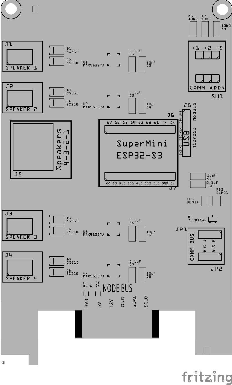
![]()
| Component Identifier | Count | Type | Value | Package | Purpose | Orientation |
|---|---|---|---|---|---|---|
| Capacitors | ||||||
| C1, C3, C5, C7, C9, C11, C13 | 7 | Capacitor-Ceramic | 0.1uF | 1206 SMD | Decoupling Capacitor for IC Protection | None |
| C2, C4, C6, C8, C10, C12, C14 | 7 | Capacitor-Ceramic | 10uF | 1206 SMD | Decoupling Capacitor for IC Protection | None |
| Diodes | ||||||
| D1 - D8 | 8 | Diode-Schottky | SS310 | SMD | Circuit protection from reverse current from speaker connections. | Cathode end has a white line and positioned towards PCB left edge |
| D5 | 1 | ESD Diode | PESD1CAN | SOT-23 SMD | I2C data bus electrostatic discharge (ESD) | Cathode end has a white line and positioned towards PCB left edge |
| Fuses & Protection | ||||||
| F1 | 1 | Fuse-PTC Polymer | 0.2A, 3V (or higher) | 1206 SMD | Protects overload from SD Module | None |
| F2 | 1 | Fuse-PTC Polymer | 1A, 5V (or higher) | 1206 SMD | Protects overload from audio speakers | None |
| Filters & Noise Suppression | ||||||
| FB1, FB2 | 2 | Ferrite Bead | BLM31PG121 | 1206 SMD | I2C Network Bus Data Line Noise Suppression | None |
| FB3, FB4 | 2 | Ferrite Bead | BLM31PG121 | 1206 SMD | 3V3 Noise Suppression for SD card reader and I2C display | None |
| Connectors | ||||||
| J1 - J4 | 4 | JST XH Socket or 2-Position Spring Terminal Connector | 2P, 2.54mm | PTH, vertical or horizontalPTH or Spring Terminal | Connectors to speakers | None |
| J5 | 1 | RJ45 Socket | 8P8C | PTH | Network cable (CAT5/6) connections to speakers (4 pairs). | Fits only one way |
| J6, J7 | 2 | Female Header | 19-Pin | PTH | Socket for ESP32 DevKit-C board | None |
| J8 | 1 | Female Header | 8-Pin | PTH | Required when using Micro-SD Card Reader for playing .wav files. | None |
| J9 | 1 | Female header | 2-Pin, 2.54mm | PTH | OLED Display Connection | None |
| Resistors | ||||||
| R1, R2, R3 | 3 | Resistor | 1kΩ | 1206 SMD | Used to limit the current to SW1 and MCP23017 for the I2C address | None |
| R4 | 1 | Resistor | 3.3kΩ | 1206 SMD | Current limiting for LED | None |
| R5 | 1 | Resistor | 10k Ω | 1206 SMD | Voltage Divider (high/low ends) | None |
| R6 | 1 | Resistor | 1.8k Ω | 1206 SMD | Voltage Divider (high/low ends) | None |
| Switches & Indicators | ||||||
| LED1 | 1 | LED (Red) | 2 mA | 1206 SMD | 5V Power Indicator | Reference back of LED, position cathode towards PCB left edge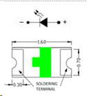 |
| JP1, JP2 | 2 | Male Header | 3P, 0.1” | PTH | Used for COMM BUS selection (I2C hardware bus) for either BUS A or BUS B. | None |
| SH1, SH2 | 2 | Jumper Cap (Shunt) | 2.54mm | - | Used to set the COMM BUS selection (JP1, JP2) | None |
| SW1 | 1 | Slide Switch | 3P, 2.54mm | PTH | Used for COMM ADDR selection (I2C address offset, 0-7). | Position ON towards PCB top edge |
| ICs | ||||||
| U1, U2, U3, U4 | 4 | Audio Amp | MAX98357A | 16TQFN | Class D audio amplifier supporting I2S connections | Small dot (pin 1) on package is positioned to PCB bottom and right edges |
| U5 | 1 | ESP32 Module | ESP32 DevKitC | DevKitC | Processes I2C text messages from the Node Card and sends player commands via UART | Position USB connection to PCB bottom edge |
| Miscellaneous | ||||||
| Micro-SD Card Reader | 1 | Module | SPI | N/A | Micro-SD Card Reader is required for playing .wav files. | |
| Micro-SD Card | 1 | SD Card | N/A | N/A | Required for storing .wav files. | N/A |
| 1 | OLED Display | SSD1309, SSD1306 | 4-Pin, I2C | Display serial messages from firmware | Refer to silk screen of OLED and card, display extends out from card. |
Tools Required
Safety Precautions
- See Safety Precautions.
Testing and Verification
The following test and verifications of the card should be performed after a through inspection of the card’s soldering. Check all of the PTH component pins and SMD pads. Make sure there are no solder bridges between pins and pads.
Visual Inspection
- Solder Joint Inspection: Use a magnifying glass or a microscope to inspect solder joints. Look for cold solder joints, insufficient or excessive solder, or any shorts between pads.
- Component Orientation: the IC’s are correctly oriented according to the PCB silkscreen or schematic.
Power-Up Tests
- Seat the Audio Card Insert the Audio Card into a tested LCC Fusion Node Bus Hub (leave speakers disconnected).
- Load firmware & insert the ESP32
- Flash the Audio Card firmware onto an ESP32 DevKit-C.
- Insert the DevKit-C into the Audio Card’s socket.
- **Power the Audio Card **
- Power the Node Bus Hub using either a tested Node Card or a Power-CAN Card.
- Quickly check for hot components; power off if anything heats abnormally.
- Self-test the Audio Card
- Attach and open a serial monitor at 115200 to the Audio Card’s ESP32 (DevKit-C on the Audio Card, not the Node Card).
- From a serial monitor, enter the command (letter)
Tto start the firmware’s self-test, then review the results.- Messages may appear on BT, OLED, or the attached serial monitor.
- See: PCB Self Testing.
- What you do: simply watch the summary—no meters or scopes required.
- Pass indicators: each tested group reports a success status.
- If any group fails: power down, re-seat the DevKit-C and Audio Card, inspect solder on the affected header/IC, and re-run.
- Tests Performed
- Audio Card Pins Test (automatic)
- I²S:
BCLK,LRCLK,DIN[1..4]driven and verified as Outputs. - SPI:
SCK,MOSI,CSas Outputs;MISOchecked as an Input. - I²C:
SDA/SCLbriefly exercised as open-drain I/O to confirm upstream Hub pull-ups and line integrity.
- I²S:
- SD Card Access Test (automatic)
- Initializes the SD interface at a conservative SPI clock, opens a small file, and reads a short block.
- What you do: insert a known-good micro-SD and observe init/read status.
- If it fails: try a different card, re-seat the socket, and re-run. (Lower SPI speed in firmware if needed.)
- Speaker Path Test (audible)
- Plays a short test-tone sequence over I²S → MAX98357A → speaker with gentle fade-in/out.
- What you do:
- Connect one speaker to the first speaker connector.
- Run the Speaker Test and listen for two distinct tones (e.g., higher tone then lower).
- For multiple amps/speakers, move the connector to each speaker connector and repeat.
- Expected result: clear, non-distorted tones at moderate volume; no pops/crackles at start/stop.
- If no sound: verify I²S header orientation, amplifier IC soldering, speaker wiring/polarity, and the 5 VDC audio rail.
- Audio Card Pins Test (automatic)
Audio Output Testing (Using Card Monitor Board)
If you connect the Audio Card’s RJ45 output to the Card Monitor Board, the LEDs will show faint flicker or shimmer in response to sound output across all eight lines.
This test is optional but can confirm that the ESP32, amplifier, and output drivers are active before connecting speakers.
| Lines | What You Should See | How to Read It |
|---|---|---|
| L1–L8 | Dim flicker or variable brightness when audio is playing | LEDs react only to the positive half of the AC audio signal. You’ll see subtle glow/flicker that follows loudness or rhythm. If all remain dark, the card is silent or inactive. |
Jumper / Ground Setup
| Item | Setting / Action | Purpose |
|---|---|---|
| JP1 (L8: GND / OUTPUT) | OUTPUT | Select OUTUT since the Audio Card does not provide a GND line on the RJ45. |
| J1 (PWR BUS GND) | Connect to the Audio Card’s supply GND | Provides the only return path so the LEDs can light. Must share the same power ground as the Audio Card (Node Bus Hub) |
Notes:
- The Audio Card does not supply GND on the RJ45 audio lines. You must connect J1 GND to the Audio Card’s power-supply ground (common return).
- LEDs are activity indicators only—they do not represent tone, volume, or fidelity.
- LEDs light only on the positive half-cycles, so flicker may be faint or uneven—this is normal.
- Speaker pair mapping: adjacent lines form pairs (e.g., L1/L2, L3/L4, L5/L6, L7/L8). In stereo builds, you’ll typically see different flicker patterns between left/right pairs.
- For meaningful audio testing (quality, channel balance), use speakers.
Tip: Use this LED check just to confirm the Audio Card is alive before you hook up speakers; faint flicker is expected.
Provisioning the Card
- See Provisioning a Card.
Troubleshooting
- See I2C Trouble Shooting.
Appendices
PCB Specifications
The card’s specifications are as follows:
![]()
| Characteristic | Value |
|---|---|
| Max Speakers | 4 |
| Max Audio Amps | 4 |
| Max Text Message Length | 16K Characters |
| Max .wav File Size | 400K1 |
| Maximum Number of Cards per LCC Fusion Node Cluster | 162 |
| LCC Fusion Node Bus Hub Connectors | 13 |
- If the ESP32 has PSRAM, the .wav file size can be up to the size of PSRAM (e.g., 2MB).
- The LCC Fusion Node Cluster can support up to 16 cards, distributed across two I2C hardware buses, with a maximum of 8 cards per bus.
- Note: This total includes all cards using the I2C address range of
0x60, as defined by the ESP32 firmware for audio.
- Note: This total includes all cards using the I2C address range of
- Connections include GND, 5V, SCL0/SDA0, and SDA1/SCL1.
How It Works
The following outlines the operational flow of the Audio Card:
The firmware of the LCC Fusion Node Card interfaces with the ESP32 on the Audio Card, leveraging the bus and address details specified in the card’s CDI I2C section.
Text-to-audio conversion:
-
Upon receiving an LCC Event-related signal, the LCC Fusion Node Card firmware sends an I2C text message to the Audio Card, instructing it to convert the text into audio for the configured audio device.
Alternatively, the Audio Card can receive text messages via Bluetooth from a Bluetooth Serial App (e.g., on a phone).
-
The ESP32 on the Audio Card uses a text-to-speech library to convert the text to audio signals and passes them to the audio amplifier via an I2S (serial) connection.
-
The audio amplifier outputs the audio signal to a speaker connected via a JST XH socket or an RJ45 socket.
Wav file playback:
-
Upon receiving an LCC Event-related signal, the LCC Fusion Node Card firmware sends an I2C message to the Audio Card, instructing it to play a specific .wav file from the micro-SD card.
Alternatively, the Audio Card can receive text messages via Bluetooth from a Bluetooth Serial App (e.g., on a phone).
-
The ESP32 on the Audio Card reads the specified .wav file (by name) from the micro-SD card reader and passes the audio data to the audio amplifier via an I2S connection.
Connections
| Component Designator | Connector Label | Connector Type | Connection Number | Description |
|---|---|---|---|---|
| J1, J2, J3, J4 | SPEAKER 1 - 4 | JST XH, Spring Terminal | 1/2, 3/4, 5/6, 7/8 | 2-wire connections to speakers |
| J5 | SPEAKERS | RJ45 Socket | 1/2, 3/4, 5/6, 7/8 | 4 pairs of connections to speakers |
| J6, J7 | SuperMini ESP32-S3 | 9-Pin Male Header | n/a | Pluggable socket for SuperMini ESP32-S3 |
| JP1, JP2 | COMM BUS | 3-Pin Male Header | A, B | COMM BUS selection (I2C hardware bus) for BUS A or BUS B. Must match configuration in the LCC Node CDI setup. |
| SW1 | COMM ADDR | Slide Switch | 1, 2, 3 | COMM ADDR selection (I2C address offset 0-7). Added to base address of MCP23017 (0x20). Configure for CDI setup. |
PCB Protection
The Audio Card converts text messages into audio signals, which are then amplified and outputted through speakers. The following is an overview of each protection component integrated into the Audio Card and its role:
![]()
| Protected Component | Protection Component | Function | Specifications | Location |
|---|---|---|---|---|
| Entire Audio Card | Polyfuse | Protects from sustained overcurrent conditions from audio peeks by increasing resistance when the 5V current exceeds 1A. Resets once the fault condition is cleared. | Hold Current: 1A | In series with the 5V input lines |
| Speaker Connectors | Diodes | Protect against reverse voltage by blocking current flow in the wrong direction. | Reverse Voltage: 100 VDC Forward Current: 3A |
In series with each input/output power connector |
| Audio Amp, SD Card Reader, I2C Display | Decoupling Capacitors | Filters out high-frequency noise and transient voltage spikes from the power supply, ensuring stable voltage to audio amp IC. | Values: 0.1 µF ceramic, 10 µF electrolytic or ceramic | Across Vcc and GND near IC. |
| I2C Lines, SD Card Reader, I2C Display | Ferrite Bead BLM31PG121SN1L | Provides high-frequency noise suppression on the I2C lines. | Impedance: 120 ohms at 100 MHz | In series with the SDA and SCL lines of the I2C bus |
| I2C Lines | ESD Protection Diode PESD1CAN | Protects the I2C lines from electrostatic discharge and voltage spikes. | Reverse Stand-off Voltage (Vr): 24 VDC Clamping Voltage (Vc): 40 VDC |
Across the SDA and SCL lines to GND |
| Speaker Connectors | SS310 Diodes | Protect against reverse voltage by blocking current flow in the wrong direction. | Reverse Voltage: 100 VDC Forward Current: 3A |
In series with each speaker connectors |
References
- Configurator’s Guides
- CDI Configuration Tool Installation Guide
- Firmware Installation Guide
- I²C Card Testing
- Serial Monitor Installation Guide
- Node Bus Hub Installation Guide
- Node Card Installation Guide
- Getting Started
- Educational Media – Understanding LCC Fusion – A Clear On-Ramp into LCC-Based Layout Automation – LCC Fusion Podcast – Fusion Hardware Architecture Overview – LCC Fusion Podcast – Cards & Node Basics
Terminology
- Amplifier
- Audio Card
- Bluetooth
- CDI
- ESP32-S3
- Event ID
- I2C
- I2S
- LCC Configuration Tool
- Micro-SD Card
- Network Cable
- Node Bus
- Node Bus Hub
- Node Card
- Polyfuse
- RJ45
- Text-to-Speech
- Voltage Divider
- WAV File
For additional terms, see the full Terminology Guide.
Notes:
(This notes table is intended for optional annotations. It can be edited directly in LibreOffice or Microsoft Word, or annotated in PDF readers that support text annotations. Empty rows may collapse in EPUB or PDF exports; this is expected.)