Block Breakout Board Assembly Guide
Table of contents
Table of contents
Introduction
The Block Breakout Board, in combination with the BOD Card and the Node Card, is used to simplify wiring for monitoring track blocks. The Block Breakout Board connects to track rails to facilitate the detection of trains (both locomotives and rolling stock) within specific track blocks. The BOD Card provides status updates via its GPIO pins to the LCC Fusion Node Card. The LCC Fusion Node Card firmware processes these updates to generate LCC events, which can then be used by other systems, such as the PWM Card, for tasks like managing signal operations based on track occupancy.
flowchart LR;
can["CAN Network"];
subgraph layout ["Train Layout"];
  direction LR;
  bod["BOD/BSD Cards (16x)"]
  nodecard[Node Card];
  track["Track Block (4x)"]
  bb[Block Breakout Board];

  track --> bb;
  bb -->|"Current <br/> (yes/no)"| bod;
  bod -->|"GPIO Output <br/> High/Low"| nodecard;
  nodecard -->|"LCC Event <br/> (occupied/unoccupied)"| can;
end;
classDef lSalmonStyle fill:#FFA07A,stroke:#333,stroke-width:2px,font-size:20px;
class bb lSalmonStyle;
classDef lightGrayStyle fill:#d3d3d3,stroke:#333,stroke-width:2px,font-size:24px;
class layout lightGrayStyle;
System Overview:
The Block Breakout Board works alongside the LCC Fusion Node Card to simplify wiring and streamline monitoring for multiple track blocks within a layout. When integrated with the BOD Card, the Block Breakout Board monitors track blocks for the presence of locomotives or rolling stock. The BOD Card detects the current flow through the tracks, indicating whether a block is occupied or unoccupied. This information is relayed to the LCC Fusion Node Card, which processes the signals via GPIO pins and generates LCC Events.
These events can be utilized by other LCC devices, such as signal control systems, to automate layout responses based on block occupancy.
Diagram Overview:
The diagram below shows how the Block Breakout Board interacts with the BOD Card, the track blocks, and the LCC Fusion Node Card to monitor both occupancy and voltage conditions.
Control Flow:
- The Block Breakout Board interfaces with the track rails to monitor the current flow.
- The BOD Card detects whether current is flowing (indicating occupancy) and outputs GPIO signals to the Node Card.
- The Node Card processes the input and generates LCC Events to update other systems on whether the block is occupied or unoccupied.
flowchart TD;
subgraph layout["Train Layout"];
	subgraph layoutbus["Track Bus"];
	  busA["TRACK BUS A"];
  	busB["TRACK BUS B"];
  end;
  direction LR;
  bb[Block<br>Breakout Board];
  bod["BOD / BSD Cards (16x)"];
  railA["RAIL A<br>(non-gapped)"];
  railB["Rail B (4x)<br>(gapped,isolated)"];

  nodeCard[Node Card];
  loco["Locomotive Motor"];

  busA --> railA --> loco --> |"current"|railB;
  railB --> |"current"|bb --> |"current"|bod --> |"current"|bb --> busB;
  bod --> nodeCard;
end;
classDef lSalmonStyle fill:#FFA07A,stroke:#333,stroke-width:2px,font-size:24px;
class bb lSalmonStyle;
classDef lightGrayStyle fill:#d3d3d3,stroke:#333,stroke-width:2px,font-size:24px;
class layout lightGrayStyle;
classDef lightblueStyle fill:lightblue,stroke:#333,stroke-width:2px,font-size:32px;
class layoutbus lightblueStyle;
Assembly and Component Placement*
This section combines both the component specifications and the assembly instructions to ensure a smooth assembly process. Below is a comprehensive list of components, their placement on the PCB, and orientation details to assist you during assembly.
Note: Components R1–R4, D1–D4, and jumpers JP1–JP4 are only required when implementing the optional Block Power Control with Trickle Detection Support.
This feature allows occupancy detection to remain active even when Track Block Rail A is turned off, by injecting a small current into the block via a 10kΩ resistor (R1–R4) and Schottky diode (D1–D4). Each jumper (JP1–JP4) enables or disables the trickle path for its respective block.
High-Level Steps for Assembly:
- PCB for the card can be ordered from any PCB fabricator using these Gerber Files.
- Clean PCB with alcohol to remove residue. See Cleaning_PCB for details.
- See also: Soldering Tips
- PCB Components - listing of components used for PCB assembly
- PCB Parts - listing of parts used for PCB assembly
Below is a list of the PCB components used for this card (see diagram before reference):
- Use of 2-pin JST XH pre-wired plugs soldered to track rail drop wires makes for easy wiring and fast connect/disconnect.
- Use of 2-position Spring Terminals (2.54mm) allow for rail drop wires to be connected directly pulling back a spring lever. These connectors can be ordered as 2-Position or assembled into a set of 2-Positions.
- Make sure this track rail has isolators creating blocks, where each block is wired to one or more of Block Breakout Boards and a BOD Card.
![]()
![]()
| Component Identifier | Count | Type | Value | Package | Purpose | Orientation |
|---|---|---|---|---|---|---|
| Capacitors | ||||||
| C1 | 1 | Capacitor-Ceramic | 0.1uF | 1206 X7R | DCC Bus Snubber (RC circuit) | None |
| Connectors | ||||||
| J1 | 1 | JST XH Socket or 2-Position Spring Terminal Connector | 4P, 2.54mm | PTH, vertical or horizontal | Connectors to track Block Rails (isolated block Rail B). | Position connection outward |
| J2 | 1 | JST XH Socket or 2-Position Spring Terminal Connector | 2P, 2.54mm | PTH, vertical or horizontal | Connector to layout’s Track Bus A & B wires | Position connection outward |
| J3 | 1 | RJ45 Socket | 8P8C | PTH | Network cable (CAT5/6) connection from BOD Card. | Fits only one way |
| J4 | 1 | Card Edge Connector | - | - | For use with Test Breakout Board. | None |
| Selectors | ||||||
| JP1-JP4 | 4 | Male Header | 2P, 2.54mm | n/a | Use Jumper Cap to boost power to the coils by using (2) 2200uF capacitors. | None |
| SH1-SH4 | 4 | Jumper Cap (Shunt) | 2.54mm | - | Used with JP1-JP4 | None |
| Diodes | ||||||
| D1-D4 | 4 | Schottky Diode | SS310 | SMA | Reverse current protection for trickle path preventing unwanted back feed between blocks or into the Track Bus. | Cathode end has a white line and positioned towards PCB left edge |
| Resistors | ||||||
| R1-R4 | 4 | Resistor | 10k Ω | 1206 SMD | Current limiting for trickle path | None |
| R5 | 1 | Resistor | 120 Ω | 1206 SMD | DCC Bus Snubber (RC circuit) | None |
| Selectors | ||||||
| JP1 | 1 | Male Header | 2-Pin, 2.54mm | PTH | Used to enable DCC Bus Snubber (one required at end of bus) | None |
| SH1 | 1 | Jumper Cap | 2.54mm | N/A | Used with DCC Bus Snubber selection. Recommend tall caps for ease of use. | None |
Tools Required
Safety Precautions
- See Safety Precautions.
Testing and Verification
Visual Inspection
- Initial Check: Examine the board for any obvious issues like missing components, solder bridges, or components that are misaligned or not fully seated.
- Solder Joint Inspection: Use a magnifying glass or a microscope to inspect solder joints. Look for cold solder joints, insufficient or excessive solder, or any shorts between pads.
- Use an Digital Multimeter (DMM) to test for continuity between:
- RJ45 socket pins (2, 4, 6, 8) and the 4 block connectors (J1, J2).
- RJ45 socket pins (1, 3, 5, 7) and the Track Bus B connector (J3)
Functional Testing
Refer to BOD Card for details on testing the Block Breakout Board with the BOD Card.
Troubleshooting
- See I2C Trouble Shooting.
Appendences
PCB Specifications
Specifications for the Block Breakout Board include:
| Characteristic | Value |
|---|---|
| Max Track Blocks | 4 |
| Max Track Current | 2750 mA1, 2 |
- Block Breakout Board uses 54mmil traces that support up to 3000 mA.
- A CAT6 network cable with 23 awg wiring is limited to <1000 mA.
How It Works
For track block occupancy detection details, refer to the BOD Card How it Works](/LccFusionProject/bod-card-assembly-guide/) section.
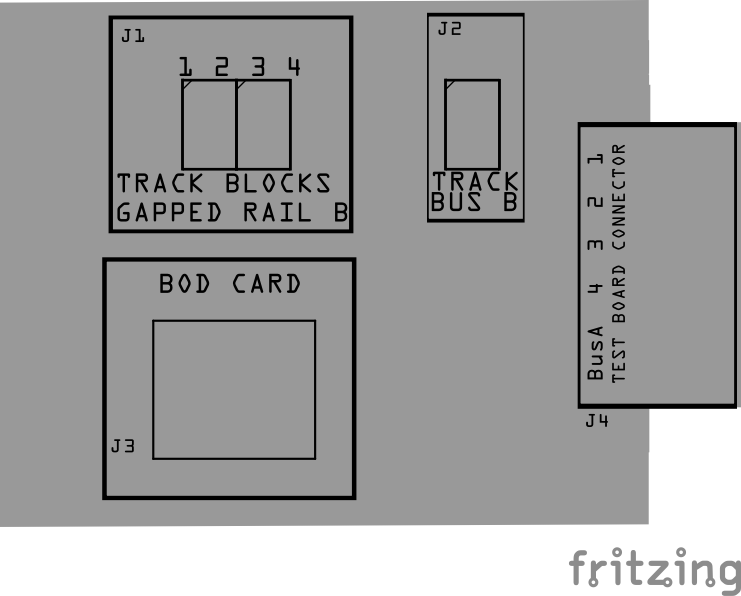
Connections
The purpose of the Block Breakout Board and its connectors is to facilitate quick and easy connections between the BOD Card and the track rails. For setups with multiple distant blocks, breakout boards can be daisy-chained together, or a network cable with a splitter can be used to provide multiple connections efficiently.
| Component Designator | Connector Label | Connector Type | Connection Number | Description |
|---|---|---|---|---|
| J1 | TRACK BLOCKS | JST XH, Spring Terminal | 1, 2, 3, 4 | Connection to insulated block rails |
| J2 | TRACK BUS | JST XH, Spring Terminal | A, B | Connection to layout Track Bus A and B wires (completes connection from track to bus) |
| J3 | BOD CARD | RJ45 Socket | 1/2, 3/4, 5/6, 7/8 | Each pin pair connects to blocks 1 thru 4. Cable to BOD Card for detection of trains, and/or cable to BLVD Card for low voltage detection caused by shorts or faulty connections. |
| J4 | TEST BOARD CONNECTOR | Card Edge | 1, 2, 3, 4, COM | Connection to Test Board for connections to the test board track |