BLVD Breakout Board Assembly Guide
Table of contents
Table of contents
Introduction
The BLVD Breakout Board, in combination with the LCC Fusion Node Card, is used to simplify wiring for monitoring track blocks. When connected to the BLVD Card, the BLVD Breakout Board helps detect low voltage conditions within a track block. The BLVD Card reports the voltage status through its GPIO pins to the LCC Fusion Node Card. The LCC Fusion Node Card firmware generates LCC events to alert the system of any low voltage conditions, allowing for appropriate corrective actions or notifications.
The BLVD Breakout Board simplifies the wiring between track blocks and BLVD Card, ensuring efficient monitoring and reporting of block conditions within the LCC Node framework.
flowchart LR;
can["CAN Network"];
subgraph layout ["Train Layout"];
  direction LR;
  blvd["BLVD Card (16x)"]
  nodecard[Node Card];
  track["Track Block (4x)"]
  bb[BLVD<br> Breakout Board];

  track --> bb;
  bb -->|"Voltage Low <br/> (yes/no)"| blvd;
  blvd -->|"GPIO Output <br/> High/Low"| nodecard;
  nodecard -->|"LCC Event <br/> (Low Voltage)"| can;
end;
classDef lSalmonStyle fill:#FFA07A,stroke:#333,stroke-width:2px,font-size:24px;
class bb lSalmonStyle;
classDef lightGrayStyle fill:#d3d3d3,stroke:#333,stroke-width:2px,font-size:24px;
class layout lightGrayStyle;
System Overview
The BLVD Breakout Board works alongside the LCC Fusion Node Card to simplify wiring and streamline monitoring for multiple track blocks within a layout. When connected to the BLVD Card, the BLVD Breakout Board monitors the voltage within the track blocks, detecting conditions where the voltage drops below a specified threshold (e.g., 12 VDC). The BLVD Card communicates this status through GPIO pins to the LCC Fusion Node Card. The Node Card processes the voltage information and generates LCC Events to notify the system of low voltage conditions. These events can be used to trigger corrective actions or provide warnings, ensuring the layout operates within safe voltage limits.
Diagram Overview:
The diagram below shows how the Block Breakout Board interacts with the BLVD Card and BLVD Card, the track blocks, and the LCC Fusion Node Card to monitor both occupancy and voltage conditions.
flowchart TD;
subgraph layout["Train Layout"];
	subgraph layoutbus["Track Bus"];
	  direction LR;
	  busA["TRACK BUS A"];
  	busB["TRACK BUS B"];
  end;
  subgraph track["Track Block"]
  	direction LR;
    railA["RAIL A<br>(non-gapped)"];
  	railB["Rail B (4x)<br>(gapped,isolated)"];
  end;
  direction LR;
  bb[BLVD Breakout Board];
  blvd["BLVD Cards (16x)"];


  nodeCard[Node Card];

	busB --> railB -.- |"voltage"|bb
	bb --> blvd
	railA -.- |"voltage"|bb
	railA -->busA;
  blvd --> nodeCard;
end;
classDef lSalmonStyle fill:#FFA07A,stroke:#333,stroke-width:2px,font-size:20px;
class bb lSalmonStyle;
classDef lightGrayStyle fill:#d3d3d3,stroke:#333,stroke-width:2px,font-size:24px;
class layout lightGrayStyle;
classDef lightblueStyle fill:lightblue,stroke:#333,stroke-width:2px,font-size:36px;
class layoutbus lightblueStyle;
Control Flow:
- Block Low Voltage Detection:
- The BLVD Breakout Board monitors track blocks for low voltage conditions when paired with the BLVD Card.
- The BLVD Card detects when voltage falls below a threshold and sends GPIO signals to the Node Card.
- The LCC Fusion Node Card processes these signals and generates LCC Events to notify other systems about voltage status, triggering warnings or corrective measures.
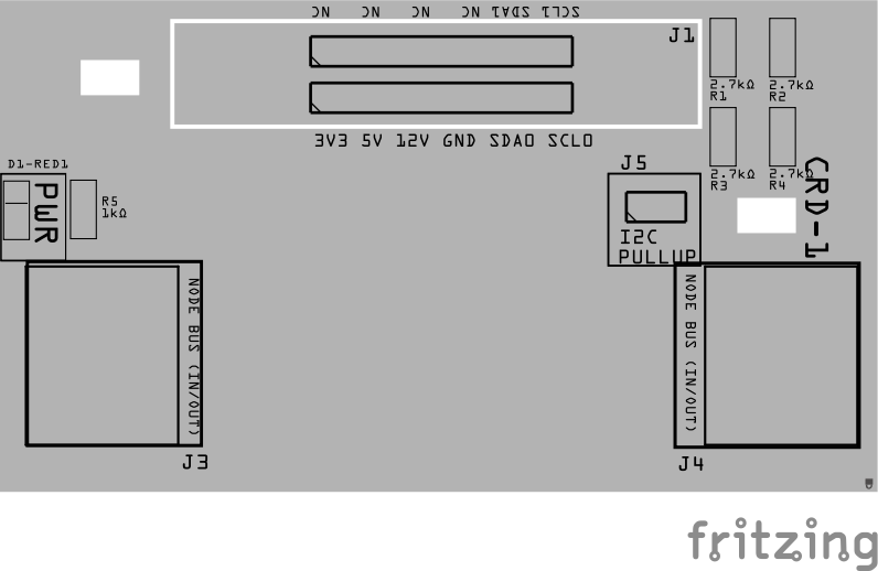
Assembly and Component Placement
This section combines both the component specifications and the assembly instructions to ensure a smooth assembly process. Below is a comprehensive list of components, their placement on the PCB, and orientation details to assist you during assembly.
![]()
High-Level Steps for Assembly:
- PCB for the card can be ordered from any PCB fabricator using these Gerber Files.
- Clean PCB with alcohol to remove residue. See Cleaning_PCB for details.
- See also: Soldering Tips
- PCB Components - listing of components used for PCB assembly
- PCB Parts - listing of parts used for PCB assembly
Below is a list of the PCB components used for this card (see diagram before reference):
- Use of 2-pin JST XH pre-wired plugs soldered to track rail drop wires makes for easy wiring and fast connect/disconnect.
- Use of 2-position Spring Terminals (2.54mm) allow for rail drop wires to be connected directly pulling back a spring lever. These connectors can be ordered as 2-Position or assembled into a set of 2-Positions.
- Make sure this track rail has isolators creating blocks, where each block is wired to one or more of BLVD Breakout Boards and a BLVD Card.
![]()
| Component Identifier | Count | Type | Value | Package | Purpose | Orientation |
|---|---|---|---|---|---|---|
| Connectors | ||||||
| J1 | 1 | JST XH Socket or 4-Position Spring Terminal Connector | 4P, 2.54mm | PTH, vertical or horizontal | Connectors to track Block Rails (isolated into block). | Position connection outward |
| J2 | 1 | JST XH Socket or 2-Position Spring Terminal Connector | 2P, 2.54mm | PTH, vertical or horizontal | Connector to Track Bus A (non-gapped Rail A). | Position connection outward |
| J3 | 1 | RJ45 Socket | 8P8C | PTH | Network cable (CAT5/6) connection from BLVD Card. | Fits only one way |
Tools Required
Safety Precautions
- See Safety Precautions.
Testing and Verification
Visual Inspection
- Initial Check: Examine the board for any obvious issues like missing components, solder bridges, or components that are misaligned or not fully seated.
- Solder Joint Inspection: Use a magnifying glass or a microscope to inspect solder joints. Look for cold solder joints, insufficient or excessive solder, or any shorts between pads.
- Use an Digital Multimeter (DMM) to test for continuity between:
- RJ45 socket pins (2, 4, 6, 8) and the 4 block connectors (J1, J2).
- RJ45 socket pins (1, 3, 5, 7) and the Track Bus connector (J3)
Functional Testing
Refer to BLVD Card for details on testing the BLVD Breakout Board with the BLVD Card.
Troubleshooting
- See I2C Trouble Shooting.
Appendences
PCB Specifications
Specifications for the Block Breakout Board include:
| Characteristic | Value |
|---|---|
| Max Track Blocks | 4 |
| Max Track Voltage | 40V |
How It Works
For details, refer to the BLVD Card How it Works section.
Connections
The purpose of the BLVD Breakout Board and its connectors is to facilitate quick and easy connections between the BLVD Card and the track rails. For setups with multiple distant blocks, breakout boards can be daisy-chained together, or a network cable with a splitter can be used to provide multiple connections efficiently.
| Component Designator | Connector Label | Connector Type | Connection Number | Description |
|---|---|---|---|---|
| J1 | TRACK BLOCKS (GAPPED RAIL B) | JST XH, Spring Terminal | 1, 2, 3, 4 | Connection to insulated block rails |
| J2 | TRACK BUS A | JST XH, Spring Terminal | 1 | Connection to non-insulated rail |
| J3 | BLVD CARD | RJ45 Socket | 1/2, 3/4, 5/6, 7/8 | Each pin pair connects to blocks 1 thru 4. Cable to BLVD Card for low voltage detection caused by shorts or faulty connections. |