BOD Card & Breakout Board Installation Guide
Table of contents
Table of contents
Overview
The Block Breakout Board interfaces the BOD Card with up to four track blocks. It supports a wide variety of devices such as sensors, buttons, LEDs, and small actuators used in model railroad automation and other low-power control applications.
What’s Needed
| Component | Purpose |
|---|---|
| Computer / RPI (3B+)1 | Runs JMRI for CAN communications with Node Card |
| Power Supply (optional)2 | Provides power to the Node Card and BOD Card (via the Node Bus Hub) |
| Node Bus Hub (or Network Cable)3 | Interfaces the Node Card with other LCC Fusion cards via the Node Bus, providing both power and communications |
| Node Card | Interfaces with CAN network and cards (via Node Bus Hub) |
| Block Breakout Board | Interfaces with track blocks, detecting current from trains |
| BOD Card | Interfaces with Node Card via serial communications and converts current detection to signals for the Block Breakout Board. |
| BOD Devices (8 max) | Sensors, buttons, LEDs, relays, or actuators |
| Network Cable (CAT5/CAT6) | Connects BOD Card to Block Breakout Board via RJ45 connector |
| 3-wire cables | Connect devices to breakout board JST XH connectors |
| Layout Power Bus (AC/DC/DCC) | Supplies breakout board power (<40 VDC, AC/DC/DCC) |
1) When using an RPi, you can simplify integration by using the RPi-CAN Card, which provides built-in CAN communication and connects directly to the LCC Fusion Node Bus—no extra wiring required. Otherwise, to run JMRI on a standalone Pi you will need:
- Raspberry Pi 3B+ (or newer): Runs JMRI for CAN communications. We recommend Steve Todd’s preconfigured JMRI image
- microSD card (8 GB or larger): Holds the JMRI OS image
- microSD card reader & imaging tool: For flashing the image to your card (e.g., balenaEtcher)
2) Powering the Node Card can be done via the CAN Bus network cable or a separate power supply 3) The Node Bus communicates via the Node Bus Hub(s) by: 1) inserting the Node Card into the Node Bus Hub board 2) connecting the Node Card to the Node Bus Hub board using a network cable
Connection Diagram
flowchart
  subgraph layout ["Train Layout"]
  	subgraph hub["Node Bus Hub (network)"]
      nodeCard[["Node Card"]]
      bodCard[["BOD Card"]]
      nodeBusHub[["Node Bus Hub (board)"]]
    end
    jmri["JMRI Software<br>CDI Config Tool"]
    computer["Computer, or <br>Raspberry PI"]
    pwrSupply(("Power Supply"))
    breakout1["Block Breakout Board"]
    breakout2["2nd Block<br>Breakout Board"]
    devices1(("Track Blocks (4x)"))
    devices2(("Track Blocks (4x)"))
    nodeCard -.-|"Plugs Into Hub for<br>Power & Communications"|nodeBusHub
		bodCard -.-|"Plugs Into Hub for<br>Power & Communications"|nodeBusHub
  end
  jmri -.- |"runs on"|computer <--> |"CAN Bus via<br>Network Cable"|nodeCard
  pwrSupply -.-> |"1+ A @ 40 v max via<br>2-wire"| nodeCard
  nodeCard <--> |"Digital I/O via<br>Node Bus Hub"|bodCard
  bodCard <--> |"Digital I/O via<br>Network Cable → J10" |breakout1
  breakout1 <-.-> |"Train Current"|devices1
  bodCard <--> |"I/O via<br>Network Cable → J11" |breakout2
  breakout2 <-.-> |"Train Current"|devices2


  classDef lightBlueStyle fill:lightblue,stroke:#2c7a2c,stroke-width:2px,font-size:16px;
 	classDef lightGreenStyle fill:lightgreen,stroke:#333,stroke-width:2px,font-size:20px;
  class hub lightBlueStyle
    class bodCard,breakout1,breakout2 lightGreenStyle
Installation Steps
-
Connect Track Bus Rail B to Block Breakout Board
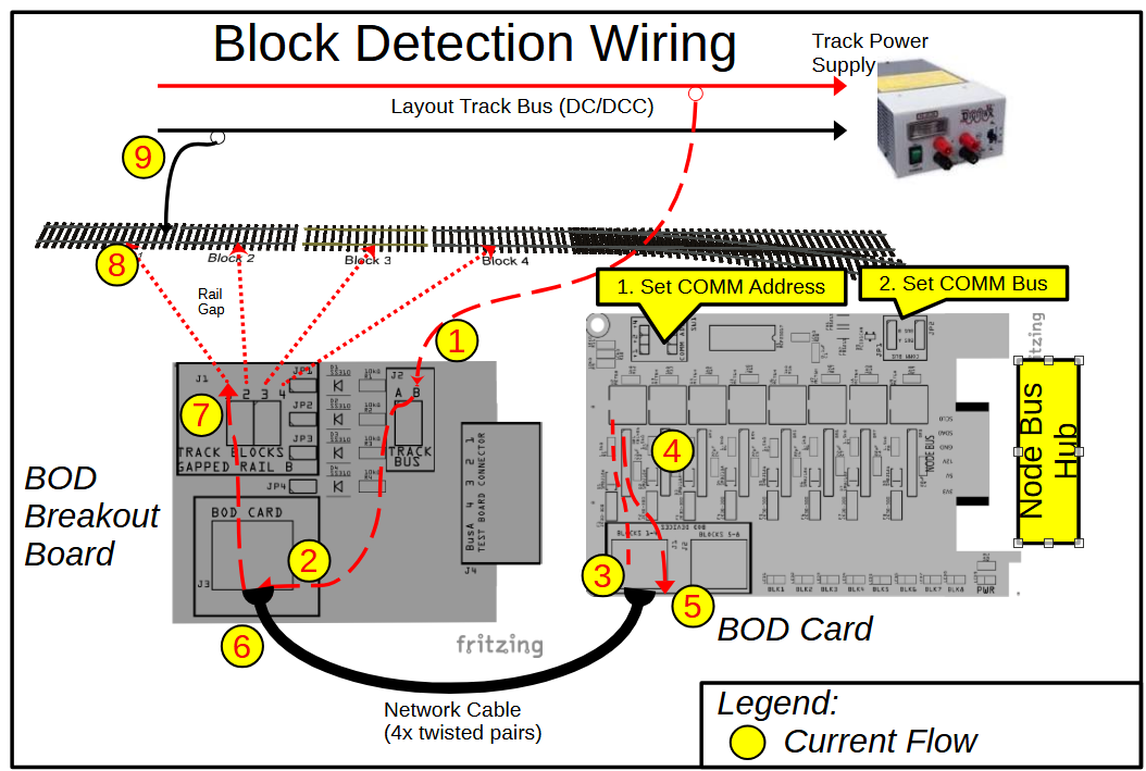
-
Connect the Block Breakout Board to the BOD Card using a standard network cable (RJ45).
- DCC Bus Snubber (JP1):
Set this jumper only if the Block Breakout is located at the end of a DCC bus run. The snubber helps dampen reflections and spikes on long wiring runs.
- Use one snubber per bus (per power district).
- Leave JP1 open if this BOD is not at the end of the bus.
💡 Tip — DCC Bus Snubber
A snubber is only needed at the end of a bus run. Use just one snubber per bus (per power district).
If more than one is enabled, it won’t usually cause damage, but it may overdamp the signal and reduce performance. - DCC Bus Snubber (JP1):
Set this jumper only if the Block Breakout is located at the end of a DCC bus run. The snubber helps dampen reflections and spikes on long wiring runs.
-
Connect up to four track blocks to the breakout board connectors
-
Connect the Layout Track Rail B to the breakout board
Track Bus Bconnector -
Set the
COMM BUSandCOMM ADDRsettings -
Configure the Node Card firmware to the BOD Card bus and address settings
Status Indicators
- BOD Card Power LED: Illuminates when 5 VDC power is present and regulated on the breakout board.
- BOD Card Block LEDs Illuminate when current is detected within a block
Testing & Troubleshooting
- Cables & Connections
- Ensure the network cable between the Digital I/O Card and Breakout Board is fully seated and oriented correctly.
- Firmware & Diagnostics
- Use the LCC Configuration Monitor (JMRI), serial console, or other diagnostic tool to check to check for block occupancy
🧰 Troubleshooting Flow
Refer to the diagrams for step-by-step guidance on isolating wiring, power, firmware, and device issues. If you reach a “Likely Bad Board” node, set the board aside for bench testing or builder support.
flowchart TD
  subgraph "Input Device Test Flow"
    direction LR
    Connect-Card("Insert BOD Card<br>in powered Node Bus Hub")
    Connect-BB("Cable BOD <br>Breakout Board to<br>BOD Card")
    Connect-Device("Connect <br>input devices <br>(buttons, sensors)<br>to connectors <br>(J1–J8)")
    Activate-Device("Activate input <br>device")

    LED-Q{"Is the Power LED ON?"}
    PWR-Q{"Measure voltage <br>at PWR BUS (J9):<br><br>Is voltage >14 V?"}
    BodCard-Detect-Q{"Is block current detected <br>(CDI Event, <br>Card I/O line low)?"}
    Simulated-Input-Q{"Temporarily place 10k resistor across rails:<br><br>Does the <br>BOD Card <br>detect the <br>current?"}

    Fix-PWR["Check layout <br>power wiring, <br>power supply <br>voltage"]
    Fix-CDI["Check BOD Card CDI <br>config information"]
    Fix-Device["Bad track connection: <br>Check track wiring"]
    Bad-Board["Likely bad<br>Block Breakout Board<br><br>Contact builder"]

    Success[" Input Device<br>Detection Verified"]

    Connect-Card --> LED-Q
    LED-Q -- "Yes, power LED is On" --> Connect-BB --> Connect-Device --> Activate-Device --> BodCard-Detect-Q
    LED-Q -- "No, power LED is Off" --> PWR-Q
    PWR-Q -- "Yes, valid input power" --> Bad-Board
    PWR-Q -- "No, invalid input power" --> Fix-PWR

    BodCard-Detect-Q -- "Yes, device detected" --> Success
    BodCard-Detect-Q -- "No, device not detected" --> Simulated-Input-Q
    Simulated-Input-Q -- "Yes, simulated input succesful" --> Fix-Device
    Simulated-Input-Q -- "No, simulated input not detected" --> Fix-CDI
    Fix-CDI --> Bad-Board
  end
    %% Color styles
  classDef question fill:#d3d3d3,stroke:#333,stroke-width:2px,font-size:16px;
  classDef error fill:#FFA07A,stroke:#333,stroke-width:2px,font-size:16px;
  classDef success fill:#c6f6c6,stroke:#2c7a2c,stroke-width:2px,font-size:16px;
  classDef action fill:lightblue,stroke:#2c7a2c,stroke-width:2px,font-size:16px;

  class LED-Q,PWR-Q,Input-Wired-Q,IOCard-Detect-Q,Simulated-Input-Q question;
  class Fix-PWR,Fix-CDI,Fix-Device,Bad-Board error;
  class Connect-Power,Connect-Card,Connect-Device,Activate-Device action;
  class Success success;
Safety Notes
- Disconnect power before making or changing device connections.
- Do not exceed device current limits; max current is limited by the 5 VDC regulator and wiring.
- Use appropriate fusing on the accessory power bus to prevent damage.
