BOD Card Configuration Guide
Table of contents
Table of contents
Introduction
The BOD Card, in synergy with the LCC Fusion Node Card and Block Breakout Board , forms the block detection functionality of the LCC Fusion Project system, facilitating the detection of trains in a track block. This integration is pivotal for automating track signaling and control, core features in advanced model railroad setups.
Application Scenarios
Below are detailed scenarios for deploying and configuring the BOD Card:
| Scenario | BOD Card Setup | Block Breakout Board Configuration | Wiring | CDI Setup |
|---|---|---|---|---|
| Train Detection for Signals | 1. Adjust COMM BUS jumpers (JP1, JP2) to BUS A. 2. Configure COMM ADDR switches (SW1) to 0 (set all switches to OFF). |
Not applicable | 1.Connect the track blocks’ ground (COM) rail to the Block Breakout Board’s BLK1 connector. 2. Connect the layout’s track bus ground (GND, COM) wire to the Block Breakout Board’s TRACK BUS (GND, COM) connection. 3. Connect the Block Breakout Board to the BOD Card using a network cable. 4. Slot the LCC Fusion Node Card and the BOD Card into a Node Bus Hub. |
1. Start the LCC CDI configuration tool. 2. Access the LCC Node configuration. 3. Navigate to the BOD Card section. 4. Enter 01 for Reference ID.5. Input Block 0 for Description.Remember to use the predefined Event IDs for scenarios requiring block occupation information, such as signal logic and conditions. |
Configuration Summary
To configure an BOD Card for use with LCC Fusion Project, follow these steps, as outlined in the documentation that follows:
-
Connect to LCC Fusion Node Card: Ensure the BOD Card is properly connected to an LCC Fusion Node Card. The system supports up to 16 BOD Cards per LCC Fusion Node Cluster, expanding your control capabilities across numerous output devices.
-
Set the card configuration selections, see below and Setting hardware communications for details.
-
Connect to Track Blocks using one of the following methods:
- Using Block Breakout Board:
- Use a network cable to connect from the BOD Card to the Block Breakout Board.
- Connect track block GND (COM) rail to the breakout board corresponding Block GND connector.
- Connect the track bus GND connection to the breakout board’s Track Bus GND connector.
- Use a network cable to connect from the BOD Card directly to track block rail(s) and Track Bus GND. Note that each block requires 2 wire to be connected from the network cable, one to the track’s GND (COM) rail and the 2nd wire to the Track Bus GND
- Using Block Breakout Board:
BOD Card Hardware Configuration Details
This section will cover the specifics of setting up the physical jumpers on the BOD Card. It includes instructions on how to access the jumpers, detailed explanations of their functions, and guidance on configuring them for various operational modes.
| Label | PCB Components Indicator | Choices | Description |
|---|---|---|---|
| COMM BUS | JP1, JP2 | BUS A, BUS B | Selects the I2C bus, aligning with firmware settings. Must match with the firmware configuration (see below). |
| COMM ADDR | SW1 | 0 - 7 | Assigns a unique I2C address within an LCC Fusion Node Cluster. Each card within an LCC Fusion Node Cluster using the same IC must have a unique address. |
BOD Card firmware Configuration for LCC Events
This part will detail the process for configuring the firmware to handle LCC events related to the I/O card. Using the LCC Configuration Tool, it will outline steps to integrate the card with the LCC Fusion firmware, setting up LCC Event IDs to drive output devices. 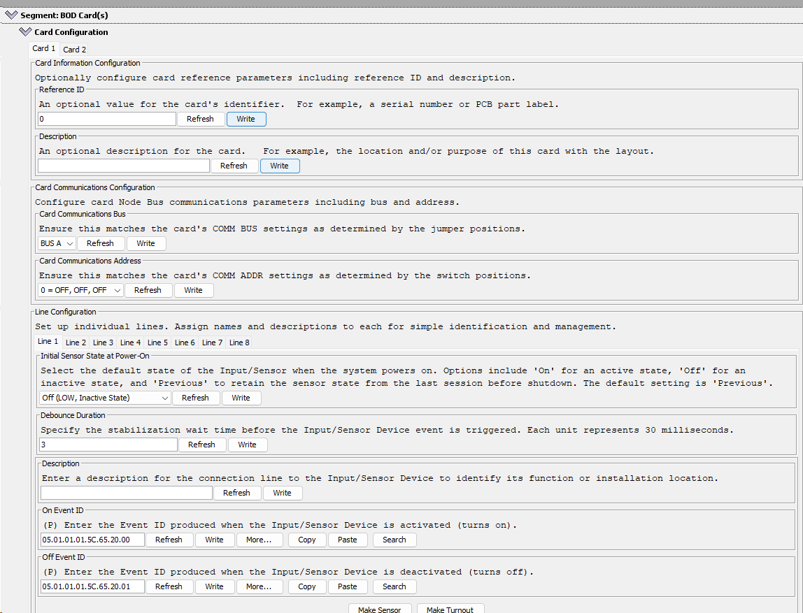
- Using the LCC Configuration Tool find the LCC Node and open the configuration.
- Scroll down to the BOD Card segment and click on the twistie to open the configuration dialog box for the card
- Select the tab for the specific card to be configured. Note that uninstalled cards can be configured for future use.
- Select the tab for the specific line to be configured. Note that unconnected lines can be configured for future use.
- Make changes and click Write to save the change.
- After all changes are made, click Refresh to verify changes took affect.
Below are the card dialog configuration options for this card (refer to diagram on right):
After changing fields, click the Write button to save the changes.
CDI Summary
The configuration interface dialog (see image on right) for a Block Occupancy Detector (BOD) Card, as presented in the JMRI Configuration Tool, includes several sections that allow for the customization and setup of the card within a model railroad environment:
- Card Information Configuration:
- Referenced ID: This field is for entering a unique identifier for the card, like a serial number or PCB component label.
- Description: Here you can enter a description of the card’s function or its purpose within the layout, which might include its location or the specific track block it monitors.
- Card Communications Configuration:
- Card Communications Bus: This dropdown is for selecting the communication bus used by the card, ensuring it matches the bus system of the layout.
- Card Communications Address: This field is for setting the card’s COMM address, which must correspond to the jumper or switch settings on the physical card.
- Line Configuration:
- Here you can assign names and descriptions to individual lines on the BOD Card. Each line corresponds to a track sensor input.
- Initial Sensor State at Power-On:
- This setting determines the default state of the Input/Sensor when the system is powered on. Options include ‘On’ for active, ‘Off’ for inactive, and ‘Previous’ to retain the state from before the system was last shut down.
- Debounce Duration:
- This value sets the stabilization wait time before the Input/Sensor Device event is triggered to avoid false detections due to noise. The duration is in increments of 30 milliseconds.
- Description (under Line Configuration):
- A field for providing a description for each line, which could detail the function or physical location of the Input/Sensor device connected to that line.
- OnEvent ID and OffEvent ID:
- These fields are for entering the Event IDs that are produced when the Input/Sensor Device is activated or deactivated. Event IDs are structured in a standardized format and are used for event mapping and action triggering within the LCC network.
This interface allows for detailed customization of the BOD Card, which is critical for precise operation in a model railroad setup, ensuring that the card correctly interprets track occupancy and communicates with other devices in the LCC network for automated control and signaling.
Getting Started
Below are practical guidelines for starting out with the BOD Card configuration:
- Utilize Default Event IDs: Starting with the default Event IDs simplifies the initial setup and minimizes reconfiguration in case of a CDI factory reset. This approach provides consistency and ease of management, especially first leaning LCC or the JMRI Configuration Tool.
- Default Values for Debounce and Initial Sensor State: Use default settings for debounce duration and initial sensor state which offsers a straightforward configuration process and ensures that the system operates predictably right after setup. The default debounce setting helps to avoid false positives from noise, and the default sensor state ensures that the system’s initial status is known and consistent.
- Simple and Clear Descriptions: Provide clear descriptions for the card and each line is crucial. The card description should briefly explain its role, while line descriptions should precisely identify which track block is being monitored. This clarity is vital for troubleshooting and for understanding the card’s role within the larger context of the layout.
By following these guidelines, you can achieve a basic yet functional setup that is easier to test and verify. The BOD Card’s design, as the simplest to configure, wire, and test, supports users in quickly getting started with layout automation. Encouraging users to start with these settings also makes the learning curve less steep, and once they’re comfortable with the basics, they can delve into more complex customizations if needed.
CDI Details
| CDI Group | CDI Field | Choices | Comments |
|---|---|---|---|
| Card Information Configuration | Reference ID | 0-255 | An optional value for the card’s identifier. For example, a serial number or PCB component label. |
| Card Information Configuration | Description | Text | You can optionally enter reference information here to describe this card. For example, the location and/or purpose of this card with the layout. |
| Card Communications Configuration | Card Communications Bus1 | BUS A, BUS B | Ensure this matches the card’s COMM BUS settings as determined by the jumper positions. |
| Card Communications Configuration | Card Communications Address1 | 0 - 7 | Ensure this matches the card’s COMM ADDR settings as determined by the switch positions. |
| Line Configuration | Description | Text | Enter a short description for this BOD device to easily identify its purpose or the connected device. For example, the location and/or purpose of the track block within the layout. |
| Line Configuration | On Event ID | Event ID | Enter the Event ID to be produced with the block is first occupied. |
| Line Configuration | Off Event ID | Event ID | Enter the Event ID to be produced with the block becomes cleared. |
| Line Configuration | Initial Sensor State at Power-On | OFF, ON, PERVIOUS | Select the default state of the Input/Sensor when the system powers on. Options include ‘On’ for an active state, ‘Off’ for an inactive state, and ‘Previous’ to retain the sensor state from the last session before shutdown. The default setting is ‘Previous’. |
| Line Configuration | Debounce Duration | 0-255 | Specify the stabilization wait time before the sensor device is triggered, where unit is 30 ms. |
- For details on bus and address selections, refer to HW Communications Configuration
Functional Testing
After configuring your BOD Card and ensuring all hardware connections are properly established, it’s essential to verify the functionality the detection of each track block to ensure your setup works as intended for your model railroad automation. Follow these steps to conduct functional testing:
- Make all of the connections between the LCC Fusion Node Card, BOD Card, Block Breakout Board, Track Bus (GND) and track block rails.
- Verify Device Behavior:
- Open an LCC Event Monitoring tool such as the one provided by JMRI.
- Place an locomotive on the rails within the track’s block and turn on the track power.
- The configured On Event ID for the specific should now appear in the event monitor.
- Turning off the track power or removing the locomotive from the track block should produce the configured Off Event ID.
- Repeat the above for each of the Block Breakout Board’s track block connectors.
Troubleshooting Guide
| Issue | Possible Cause | Solution |
|---|---|---|
| No power to track block | Incorrect connections to track | 1. Verify Track Bus, track block rails, and Block Breakout Board connections. 2. Block Breakout Board not connected to track block’s GND/COM rail. 3. Block Breakout Board not connected to Track Bus GND/COMM connector. 4. Track Bus VDC+ not connected to track block VDC+ rail. |
| BOD Card block indicator not showing detection. | LCC Fusion Node Card not connecting to BOD Card. | 1. Verify that LCC Fusion Node Card is powered up 2. Verify that BOD Card is seated in the Node Bus Hub connector. 3. Verify via the LCC Node Serial Monitor that the BOD Card is detected. |
| BOD Card is not connecting | Incorrect HW Communications Bus and Address | 1. Confirm the HW Communications Bus and Address matches between the card and the configuration tool. If encountering this, check that the HW Communications Bus and Address settings align between the card and the configuration tool. 2. Utilize the LCC Fusion Node Cluster Serial Monitor to inspect currently detected I2C devices within the LCC Fusion Node Cluster network. |