Breakout Board Assembly Guides
Table of contents
Table of contents
Introduction
LCC Fusion Project refers to some of the PCB (boards) as Breakout Boards, which provide specific functions for adding layout automation. Breakout Boards are connected to both the LCC Fusion Project Cards and the I/O devices on the layout. These breakout boards typically have best suited for the type of device being connected. For example, the Block Breakout Board is connected to a BOD Card using a network cable inserted into an RJ45 socket and also connected the track blocks using JST or spring terminal connectors.
For detailed information on design best practices and considerations, please see the PCB Design Guidelines section in our documentation.
LCC Fusion Breakout Boards: From Start to Finish
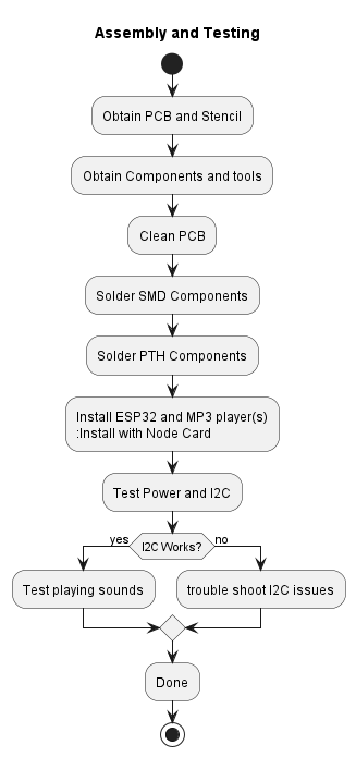 Below, you’ll find links to specific guides for PCB LCC Fusion Breakout Boards included in the LCC Fusion Project. These guides are tailored to the unique aspects of assembling each type of PCB, yet they all follow the same fundamental principles outlined in our sequence diagram. This consistency ensures that, no matter which PCB you’re working on, the process remains familiar and straightforward.
Sequence of Activities:
-
Preparation: Gathering the necessary tools and components.
-
Soldering: Step-by-step instructions for soldering components onto the PCB.
-
Testing: Guidelines for testing the PCB to ensure functionality.
-
Integration: Advice on integrating the assembled PCB into your model railroad layout.
-
Troubleshooting: Common issues and how to resolve them.
Required LCC Fusion Breakout Boards
| LCC Fusion Breakout Boards | Description |
|---|---|
| Node Bus Hub | Provides connectivity between BOD Card and LCC Fusion Cards . |
Optional LCC Fusion Breakout Boards
| LCC Fusion Breakout Boards | Description |
|---|---|
| Block Breakout Board | Provides connectivity between BOD Card and Track Block . |
| DC Motor Driver Breakout Board | Provides connectivity between PWM Card and DC Motors. Provides connectivity between DCC Card and cab’s DCC decoders. |
| Stepper Motor Breakout Board | Provides connectivity between Digital I/O Card and stepper motors. |
Additional Materials:
Supplies
-
PCB Components - listing of components used for PCB assembly
PCB Parts - listing of parts used for PCB assembly
How To Guides
[Builder’s Resources & Tips](/LccFusionProject/tips
Table of contents
- 6x Node Bus Hub Assembly Guide
- Node Bus Hub Repeater Assembly Guide
- BLVD Breakout Board Assembly Guide
- Block Breakout Board Assembly Guide
- Card Output Monitor Board Assembly Guide
- DC Motor Driver Breakout Board Assembly Guide
- Digital I/O Breakout Board Assembly Guide
- Digital Sensor Breakout Board Assembly Guide
- NeoPixel Breakout Board Assembly Guide
- Node Analog Sensor Breakout Board Assembly Guide
- Relay Breakout Board Assembly Guide
- Servo Motor Driver Breakout Board Assembly Guide
- Signal Masts Breakout Board
- Stepper Motor Driver Breakout Board Assembly Guide
- Turnout Coil Switch Machine Breakout Board Assembly Guide
- Turnout Servo Switch Machine Breakout Board Assembly Guide
- Turnout Slow Motion Switch Machine Breakout Board Assembly Guide
- Turnout Stall Motor Switch Machine Breakout Board Assembly Guide
- UOD Breakout Board Assembly Guide
- SuperMini I/O Status Shield Assembly Guide