Card Output Monitor Board Assembly Guide
Table of contents
Table of contents
Introduction
The Card Output Monitor Board is a diagnostic tool designed for use with the LCC Fusion system. It connects between any LCC Fusion I/O card and its corresponding breakout board using standard RJ45 cables. Its purpose is to help users verify proper wiring, signal activity, and voltage levels on all 8 lines of the system’s internal cable connections.
The board features visual LED indicators that show:
- Line Activity (L1–L6): One LED per line to indicate signal status — logic high/low, PWM, analog, or audio-frequency activity depending on the card type
- Power Status (L7): Whether power is present on the line (e.g., 5V, 12V, Track VDC)
- Ground Status (L8): Whether a valid ground reference is present
This makes it easy to:
- Confirm that a breakout board is correctly connected
- Detect missing or incorrect ground and power lines
- Visually identify whether each line is idle, active, or behaving abnormally
- Troubleshoot cable issues, reversed cards, or firmware errors
The Card Output Monitor Board is especially useful during layout debugging, bench testing, or field installation. It supports all standard LCC Fusion cards, including sensor, turnout, audio, PWM, and detection cards.
By observing LED patterns — such as steady on, blinking, or off — users can interpret the health and activity of the connection at a glance. The board may also include an onboard ESP32-S3 (SuperMini) to provide smarter signal interpretation and LED behavior for advanced monitoring scenarios.
Quick Guide
- Plug the RJ45 from the card into the Card Output Monitor Board.
- Power the card as usual.
- Watch LEDs per the section below for your card type.
Legend
- Always On – this line is a power source
- Usually Off – turns on only when that line is active
- Blinks/Varies – activity/pulsing (PWM, audio, CAN traffic)
- Never On – ground (ok if dark)
- Selectable – depends on a card/jumper setting
Button Card (buttons are inputs; LEDs wired to monitor GND)
| Lines | What you should see | How to read it |
|---|---|---|
| L1–L7 | ON (when ON event is sent) | LEDs will go on/off based on Events received |
| L8 | Either: Always off (if configured as GND) ON at rest → OFF when pressed (if configured as I/O) |
Line 8 can be set as a normal input like the others, or as a ground reference for the button set. |
- Configure Line 7 using the card’s L7 jumper (JP2) as I/O
- Configure Line 8 using card’s L8 jumper (JP1) to either GND or I/O
PWM Card (dimming, motor/servo drive on logic lines)
| Lines | What you should see | How to read it |
|---|---|---|
| L1–L6 | Flicker or brightness changes | Normal PWM activity |
| L7 | Either: On (5 VDC or 12 VDC) (if configured as PWR) Flicker or brightness changes (if configured as PWM) |
Line 7 can be set as a normal PWM like the others, or as power for PWM devices. |
| L8 | Either: Off (if configured as PWR) Flicker or brightness changes (if configured as PWM) |
Line 8 can be set as a normal PWM like the others, or as a ground reference for PWM devices. |
Configure L8 using card’s LINE 8 jumpers (JP1 / JP2) to either PWM or PWR
Sensing Cards (Sensor Card, Node Card I/O)
| Lines | What you should see | How to read it |
|---|---|---|
| L1–L6 | Two common behaviors: • Active-LOW (most 2-wire switches & many 3-wire sensors): ON at rest → OFF when triggered (line pulled to GND) • Active-HIGH (some 3-wire modules like many HTTM touch): OFF at rest → ON when triggered (line driven HIGH) |
Each line is a logic input from the sensor back to the MCP23017 → Node Card. Firmware can set pull-ups and interpret active-LOW/HIGH. 2-wire: one side to GND, other to the Signal line (internally pulled up) → press = LOW. 3-wire: V/G/S from the Sensor Breakout (module drives the Signal line). |
| L7 | Always On (when enabled) | Power (5V) for 3-wire sensor modules. |
| L8 | Never On | Ground for sensors (return). LED won’t light by design. |
Notes & tips • For 2-wire switches (e.g., reed, simple pushbutton used as a sensor): the LED goes dark when closed (active-LOW). • For 3-wire active-HIGH modules (e.g., many HTTM touch sensors), the LED lights when triggered. • For 3-wire active-LOW modules (e.g., many IR beam-break boards), the LED turns off when the beam is broken. • Plug the optional GND lead into the Card Output Monitorwhen testing sensors so the LEDs have a solid return path. • L7 voltage (3.3 VDC vs 5 VDC) should match your sensor module spec.
Turnout Card (stall motor drive with point sense lines)
| Lines | What you should see | How to read it |
|---|---|---|
| L1–L2 | or (alternates polarity) | One LED lights when motor is driven one way, the other LED when driven the opposite way. |
| L3–L4 | → when that point is set | Point sense feedback: LED turns on to indicate closed or thrown position. |
| L5–L6 | or (alternates polarity) | Second half of motor drive (mirrors L1/L2). |
| L7–L8 | → when that point is set | Point sense feedback: LED turns on to indicate closed or thrown position. |
Notes:
- These cards require the optional GND connection on the Card Monitor. Without it, the LEDs won’t light.
- During a throw, you’ll see LEDs on L1/L2 or L5/L6 change as the motor drives.
- When the turnout stops, one of the point sense lines (L3/L4 or L7/L8) will remain lit, showing the turnout’s final position.
Track / Detection Cards (BOD, BLVD, BRD, POD, UOD)
| Lines | What you should see | How to read it |
|---|---|---|
| L1–L8 | LED ON when detection is active LED OFF when no detection |
Each line corresponds to one detection line (e.g., block occupied vs. clear). |
Notes:
- These cards require the optional GND connection on the Card Monitor. Without it, the LEDs won’t light.
- During testing, you’ll see each LED toggle ON when the card senses a block/train (or simulated short), and OFF when clear.
Assembly and Component Placement
This section combines both the component specifications and the assembly instructions to ensure a smooth assembly process. Below is a comprehensive list of components, their placement on the PCB, and orientation details to assist you during assembly.
High-Level Steps for Assembly:
- PCB for the card can be ordered from any PCB fabricator using these Gerber Files.
- Clean PCB with alcohol to remove residue. See Cleaning_PCB for details.
- See also: Soldering Tips
- PCB Components - listing of components used for PCB assembly
- PCB Parts - listing of parts used for PCB assembly
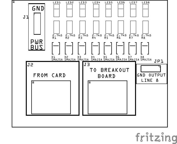
Below is a list of the PCB components used for this card (see diagram before reference):
![]()
![]()
| Component Identifier | Count | Type | Value | Package | Purpose | Orientation / Notes |
|---|---|---|---|---|---|---|
| Resistors | ||||||
| R1–R8 | 8 | Resistor | 2.7 kΩ | SMD 1206 | Current limit for each line’s LED | None |
| LEDs | ||||||
| LED1 - LED8 | 8 | LED | Red or Green | SMD 1206 | Visual indicator for each line (L1–L8) | Cathode toward board Top edge |
| Per-line protection | ||||||
| D1 - D8 | 8 | TVS diode (unidirectional) | SMAJ5.0A | SMA | Clamp spikes at the LED node (after R) | Cathode toward board Top edge |
| Connectors | ||||||
| J1 | 1 | JST XH Socket or 2-Position Spring Terminal Connector | 1P, 2.54mm | PTH, vertical or horizontal | Optional layout GND when Line 8 is not used as GND | None |
| J2 | 1 | RJ45 (IN) | - | 8P8C, PTH | Input from card under test | Fits only one way |
| J3 | 1 | RJ45 (OUT, passthrough) | - | 8P8C, PTH | Daisy-chain to breakout/device | Fits only one way |
| Selectors | ||||||
| JP1 | 1 | Male header | 3P, 2.54 mm | PTH | Select Line 8 as GND (board return) or CH8 (eighth signal line) | None |
Tools Required
Safety Precautions
- See Safety Precautions.
Testing and Verification
Visual Inspection
- Initial Check: Examine the board for any obvious issues like missing components, solder bridges, or components that are misaligned or not fully seated.
- Solder Joint Inspection: Use a magnifying glass or a microscope to inspect solder joints. Look for cold solder joints, insufficient or excessive solder, or any shorts between pads.
- Use an Digital Multimeter (DMM) to test for continuity between:
- RJ45 socket pins (2, 4, 6, 8) and the 4 block connectors (J1, J2).
- RJ45 socket pins (1, 3, 5, 7) and the Track Bus connector (J3)
Functional Testing
Refer to BLVD Card for details on testing the BLVD Breakout Board with the BLVD Card.
Troubleshooting
- See I2C Trouble Shooting.
Appendences
PCB Specifications
| Characteristic | Value / Description |
|---|---|
| Supported Lines | 8 (L1–L8) |
| Supported Voltages | 3.3 VDC – 12 VDC DC (compatible with Node, Sensor, Output, PWM, and Turnout Cards) |
How It Works
The Card Output Monitor Board is a universal diagnostic tool that connects between any LCC Fusion card and its breakout board using standard RJ45 cables. Each of the eight lines (L1–L8) drives its own LED circuit through a 2.7 kΩ resistor, providing a quick visual indication of voltage or PWM activity on that line.
- LED indication:
- Steady ON → line HIGH or powered.
- OFF → line LOW or inactive.
- Flicker → PWM or pulse activity.
- Protection: Each LED node is protected by a SMAJ5.0A TVS diode to absorb transient spikes or reverse-polarity events without loading the card output.
- Ground return:
- If the card provides GND on L8, set JP1 = GND so all LEDs share that return path.
- If L8 is used as a line or power line, set JP1 = CH and connect a separate GND lead to J1 (PWR BUS GND).
The LEDs show logic state, power presence, or PWM brightness, allowing installers and builders to confirm wiring integrity and signal activity without using a meter or oscilloscope.Connections
The purpose of the BLVD Breakout Board and its connectors is to facilitate quick and easy connections between the BLVD Card and the track rails. For setups with multiple distant blocks, breakout boards can be daisy-chained together, or a network cable with a splitter can be used to provide multiple connections efficiently.
Connectors
| Component Designator | Connector Label | Connector Type | Connection Number | Description |
|---|---|---|---|---|
| J1 | POWER BUS | JST XH, Spring Terminal | GND | Connection to insulated block rails |
| J2 | FROM CARD | RJ45 Socket | 1-8 | Connection to non-insulated rail |
| J3 | TO BREAKOUT BOARD | RJ45 Socket | 1/2, 3/4, 5/6, 7/8 | Each pin pair connects to blocks 1 thru 4. Cable to BLVD Card for low voltage detection caused by shorts or faulty connections. |
Voltage Reference Table
This table provides a quick guide to understanding voltages on the Card Output Monitor Board based voltage present on each line. Each line corresponds to a specific role—such as ground, power (like 5V or 3.3V), or an ADC signal.
| Card Type | Signal Type | When Line Voltage Present | L1 | L2 | L3 | L4 | L5 | L6 | L7 | L8 |
|---|---|---|---|---|---|---|---|---|---|---|
| Audio Card | AC | Sound | Audio (AC) | Audio (AC) | Audio (AC) | Audio (AC) | Audio (AC) | Audio (AC) | Audio (AC) | Audio (AC) |
| BLVD Card | Digital | Detection | Track VDC | Track VDC | Track VDC | Track VDC | Track VDC | Track VDC | Track VDC | Track VDC |
| BOD Card | Digital | Detection | Track VDC | Track VDC | Track VDC | Track VDC | Track VDC | Track VDC | Track VDC | Track VDC |
| BRD Card | Digital | Detection | Track VDC | Track VDC | Track VDC | Track VDC | Track VDC | Track VDC | Track VDC | Track VDC |
| Button Card | Digital | Pressed | 5V | 5V | 5V | 5V | 5V | 5V | 5V | 5V or 0V (selectable) |
| Digital I/O Card (configured for output only) | Digital | Line = HIGH | 5V | 5V | 5V | 5V | 5V | 5V | 5V | 5V or 0V (selectable) |
| LCC CAN Bus Network Cable | Digital | Line = HIGH | ~2.5V (CAN-H) | ~2.5V (CAN-LOW) | 0V | N/A | N/A | 0V | 0V | V12+ |
| Node Card I/O | Digital | Line = LOW (GND) | 3.3V/ADC | 3.3V/ADC | 3.3V/ADC | 3.3V/ADC | 3.3V/ADC | 3.3V/ADC | 3.3V/ADC or 5V (selectable) |
3.3V/ADC or 0V (selectable) |
| Output Card | Digital | Line = HIGH | 9V/12V | 9V/12V | 9V/12V | 9V/12V | 9V/12V | 9V/12V | 9V/12V | 9V/12V, 0V |
| POD Card | Digital | Detection | 5V | 5V | 5V | 5V | 5V | 5V | 5V | 5V, |
| PWM Card | PWM | Line = HIGH | 5V/12V PWM | 5V/12V PWM | 5V/12V PWM | 5V/12V PWM | 5V/12V PWM | 5V/12V PWM | 5V/12V PWM | 5V/12V PWM, 0V |
| Sensor Card | Digital | Line = LOW (GND) | 5V | 5V | 5V | 5V | 5V | 5V | 5V | 0V |
| Sound Card | AC | Sound | Audio (AC) | Audio (AC) | Audio (AC) | Audio (AC) | Audio (AC) | Audio (AC) | Audio (AC) | Audio (AC) |
| Turnout Card | PWM | Line = HIGH | 9V/12V | 9V/12V | 5V | 5V | 9V/12V | 9V/12V | 5V | 5V |
| UOD Card | Digital | Detection | 5V | 3.3V | 3.3V | 3.3V | 3.3V | 3.3V | 5V | 0V |