Yard Distant Signal Example
Table of contents
Table of contents
Introduction
This example shows both the Mast and Logic configurations for a simple 2-lamp yard distant signal.
Mast Configuration
Below is a table showing the configuration of the 2-lamp dwarf signal, with two aspects; Caution and Clear The configuration assumes the signal is plugin to an LCC Fusion Signal Breakout Board, where line 1 is connect to a yellow lamp, and line 2 is connected to a green lamp. This Signal Breakout board is cabled to a PWM Card, configured for communications address 0 (slide switches are off, off, off) on BUS A. Since this our only mast for the Node, we’ll configure it as Mast 1.
Card Information Configuration
Use the Card Information Configuration section to specify which physical PWM card drives this mast: its Node ID and card number locate the correct controller on the CAN network, while the Reference ID and Description label it in your layout. The Communications Bus and Address fields reflect the jumper and switch settings that must match the card’s hardware configuration.
| Field | Value | Comment |
|---|---|---|
| Card Node ID | 05.01.01.01.5C.66 | Node ID of the PWM card’s controlling Node Card |
| Card # | 1 | First PWM card defined on this node |
| Card Reference ID | PWM.001 | Hardware reference label for this PWM Card |
| Card Description | Main Yard | Area served by this PWM Card |
| Card Communications Bus | BUS A | Jumper setting on the PWM Card for its COMM BUS |
| Card Communications Address | 0 = OFF, OFF, OFF | Three slide switches on PWM Card set to OFF, OFF, OFF for COMM ADDR |
Mast Configuration
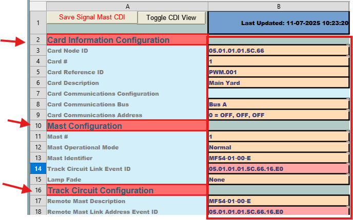 Use the Mast Configuration section to define the core parameters for each signal mast—its unique number, operational mode, identifying name, and how it links back to its associated track circuit. These fields ensure the mast is properly addressed on the layout bus, tied to the correct block detector, and behaves as expected when its rules fire.
| Field | Value | Comment |
|---|---|---|
| Mast # | 1 | Mast number (1–8). Must be unique per Node. |
| Mast Operational Mode | Normal | Indicates an active, independent mast. |
| Mast Identifier | MF54‑01‑00‑E | Standardized name identifying this signal (zone/location). |
| Track Circuit Link Event ID | 05.01.01.01.5C.66.16.E0 | Event ID used to link this mast to its Track Circuit. |
| Lamp Fade | None | Default is None; select “Fade” if desired. |
Track Circuit Configuration
Use the Track Circuit Configuration section to tie this mast to its corresponding track circuit: the Remote Mast Description gives a human-friendly name for the track circuit linked to this mast, and the Remote Mast Address sets the default Event ID that the mast listens to for occupancy or speed changes on that circuit.
| Field | Value | Comment |
|---|---|---|
| Remote Mast Description | MF54‑01‑00‑E | Friendly name for the linked Track Circuit tying its linked mast. |
| Remote Mast Address | 05.01.01.01.5C.66.16.E0 | Defaults to this mast’s Track Circuit Link Event ID. |
Rule To Aspect Mapping Configuration
Use this section to define how each speed‐based rule maps to a specific signal aspect. For each rule, you’ll give it a name, set the speed threshold that triggers it, assign the Event IDs used to command and clear the aspect, and specify which lamp outputs (and their behavior) correspond to that aspect.
Rule 1
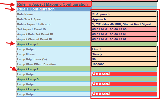 Rule 1 (“21-Approach”) defines the Approach aspect for speeds at or above the “Approach” threshold. When the Mast’s Track Circuit reports that speed, the Set Aspect Event ID (05.01.01.01.5C.66.15.00) is sent to command the yellow lamp to light, the Aspect Rule Set Event ID (05.01.01.01.5C.66.15.01) flags the aspect as active, and when the condition clears the Aspect Rule Clear Event ID (05.01.01.01.5C.66.15.02) resets it. Line 1 (the yellow lamp) illuminates steadily at 50% brightness with the configured glow duration, while all other lamps remain off.
| Field | Value | Comment |
|---|---|---|
| Rule Name | 21‑Approach | Aspect name for this rule. |
| Rule Track Speed | Approach | Speed threshold that triggers the Approach aspect. |
| Rule’s Aspect Indicator | Y, Y/R - Max 40 MPH, Stop at Next Signal | Human-readable description of this aspect. |
| Set Aspect Event ID | 05.01.01.01.5C.66.15.00 | Default Event ID for setting this aspect. |
| Aspect Rule Set Event ID | 05.01.01.01.5C.66.15.01 | Event ID fired when the aspect becomes active. |
| Aspect Rule Clear EvenD | 05.01.01.01.5C.66.15.02 | Event ID fired when the aspect clears. |
| Aspect Lamp 1 | ||
| Lamp Output | Line 1 | Lamp used for Approach (yellow). |
| Lamp Phase | Steady | Lamp remains steady on. |
| Lamp Brightness (%) | 50 | Default 50% intensity. |
| Lamp Glow Effect Duration | 1000000 | Default glow time. |
| Aspect Lamps 2-4 | ||
| Lamp Output | Unused | Remaining lamps remain off. |
Rule 2
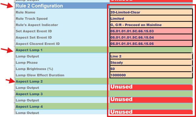 Rule 2 (“20-Limited-Clear”) defines the Limited-Clear aspect when the Mast’s Track Circuit reports the “Limited” speed threshold. At that point the sheet sends the Set Aspect Event ID (05.01.01.01.5C.66.15.03) to command Line 2 (green) to light steadily, and fires the Aspect Rule Set Event ID (05.01.01.01.5C.66.15.04) to mark the aspect as active. When the condition ends, the Aspect Rule Clear Event ID (05.01.01.01.5C.66.15.05) is sent to clear it. Lamp 2 illuminates at 50 % brightness for the configured glow duration, and all other lamps remain off.
| Value | Comment |
|---|---|
| Rule Name | 20‑Limited‑Clear |
| Rule Track Speed | Limited |
| Rule’s Aspect Indicator | G, G/R - Proceed on Mainline |
| Set Aspect Event ID | 05.01.01.01.5C.66.15.03 |
| Aspect Rule Set Event ID | 05.01.01.01.5C.66.15.04 |
| Aspect Rule Clear Event ID | 05.01.01.01.5C.66.15.05 |
| Aspect Line 1 | |
| Lamp Output | Line 2 |
| Lamp Phase | Steady |
| Lamp Brightness (%) | 50 |
| Lamp Glow Effect Duration | 1000000 |
| Aspect Lamps 2-3 | |
| Lamp Output | Unused |
Rules 3 & 4
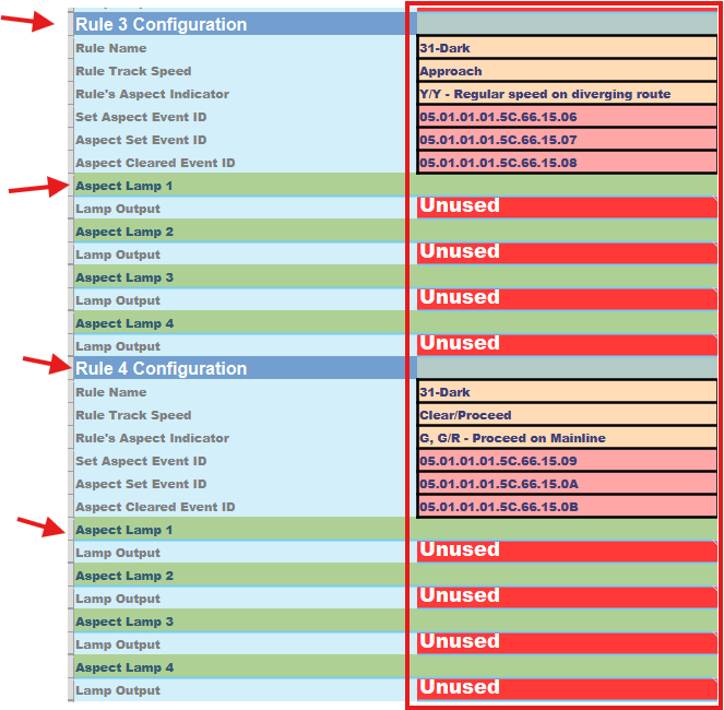 Since this distant signal only needs two aspects, Rules 3 and 4 are intentionally left unused. To skip them:
- Leave the Rule Name blank (or any value such as Dark).
- Set every Lamp Output in those blocks to Unused.
The assistant will detect that no lamps are configured and automatically skip those rule-blocks at runtime—these empty slots merely serve as placeholders should you ever need to add more aspects later.
| Field | Value | Comment |
|---|---|---|
| Rule 3 Configuration | ||
| Rule Name | Dark | Any rule name can be used since no lamps are configured (below) |
| Lamp Output | Unused | Lamp is set off |
| Field | Value | Comment |
|---|---|---|
| Rule 4 Configuration | ||
| Rule Name | Dark | Any rule name can be used since no lamps are configured (below) |
| Lamp Output | Unused | Lamp is set off |
Next: Step-by-step creation of a Logic sheet from the template, followed by a fully populated example for a simple signaling layout.
Logic Configuration
This single‐statement Logic Group watches downstream Block 1 and then sets the distant‐yard mast to Approach or Limited-Clear immediately when the block’s occupancy Event ID changes.
Node ID & Logic Number Configuration
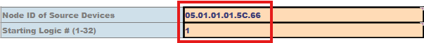 The Node ID of Source Devices sets the default Node address used for all condition Event IDs on this sheet, while Starting Logic # assigns the first statement number for this fragment—subsequent statements auto-increment from there. By picking non-overlapping start numbers across multiple sheets, you can build and restore large logic configurations in manageable pieces.
| Field | Value | Comment |
|---|---|---|
| Node ID of Source Devices | 05.01.01.01.5C.66 | Node ID associated with the node controlling the BOD Card |
| Starting Logic # (1-32) | 1 | First statement number for this sheet’s fragment (subsequent statements auto-increment); avoid overlapping ranges |
LOGIC: 1 Configuration
Condition 1
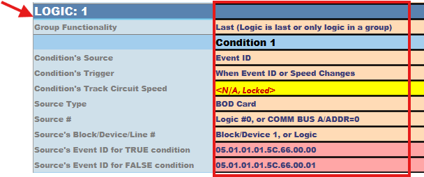 Use the Condition 1 fields to define the first input your logic statement will evaluate. Here you specify which card and Event ID the sheet should monitor, when to trigger the check, and what values mean “true” (occupied) or “false” (clear). Fill in each field so the node’s firmware for logic processing knows exactly where to look and how to interpret that input.
| Field | Value | Comment |
|---|---|---|
| Condition’s Source | Event ID | Monitor BOD Card 1 events (Bus A, Address 0) |
| Condition’s Trigger | When Event ID changes | Fire whenever the block’s Event ID updates |
| Source Type | BOD Card | Type of card being used (Block Occupancy Detection) |
| Source # | Logic #0, or COMM BUS A/ADDR=0 | Card’s communication bus and address |
| Source’s Block/Device/Line # | Block/Device 1, or Logic | Downstream block to watch |
| Source’s Event ID for TRUE | 05.01.01.01.5C.66.00.00 | Occupied Event ID (hex 00) |
| Source’s Event ID for FALSE | 05.01.01.01.5C.66.00.01 | Clear Event ID (hex 01) |
Operator
 Use the Logical Operator field to specify how multiple conditions should be combined when evaluating your statement. For a single‐condition logic (no second condition), select Condition 1 Only so that only the first input is tested.
| Field | Value | Comment |
|---|---|---|
| Logical Operator | Condition 1 Only | No second condition |
Logic Flow
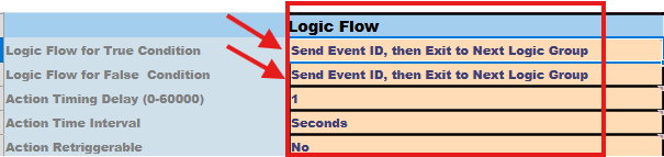 Use the Logic Flow and Timing fields to control what happens after an action fires and how it repeats:
- Logic Flow for True/False determines whether the sheet should stop evaluating further statements (exit the group) or continue when a condition is met or not.
- Action Timing Delay/Interval Retrigger lets you set delays, repeat intervals, or disable retriggers for each action branch. In this simple example both branches fire immediately and then exit the group, so no timing settings are needed.
| Field | Value | Comment |
|---|---|---|
| Logic Flow for True Condition | Send Event ID, then Exit to Next Logic Group | When condition is True, send perform a Logic Action |
| Logic Flow for False Condition | Send Event ID, then Exit to Next Logic Group | When condition is False, send perform a Logic Action |
| Action Timing Delay/Interval Retrigger | Not used since both events are sent immediately |
Logic Actions
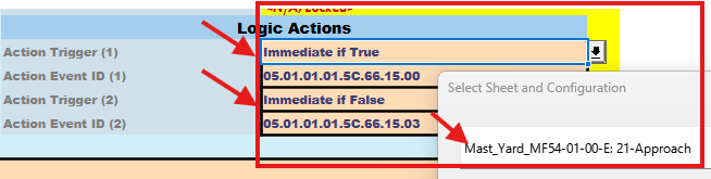 Use the Action Trigger and Action Event ID fields to define exactly when and which Event ID will be sent based on the outcome of your condition.
- Action Trigger (1) and Action Event ID (1) fire when the condition evaluates to True.
- Action Trigger (2) and Action Event ID (2) fire when the condition evaluates to False.
You can choose “Immediate” or “After delay,” and the sheet will auto-fill the correct mast-and-rule Event IDs for each branch.
| Field | Value | Comment |
|---|---|---|
| Action Trigger (1) | Immediate if True | When selected, also select the Mast and rule associated with this condition (auto fills the corresponding ) |
| Action Event ID (1) | 05.01.01.01.5C.66.15.00 | Auto filled, sets mast to Approach |
| Action Trigger (2) | Immediate if False | When selected, also select the Mast and rule associated with this condition (auto fills the corresponding ) |
| Action Event ID (2 | 05.01.01.01.5C.66.15.03 | Auto filled, sets mast to Limited-Clear |
Comments
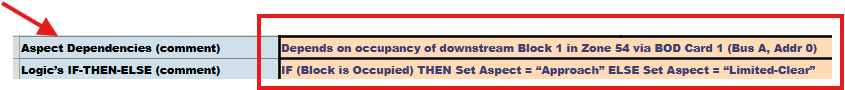 Use the final comment fields to capture human-readable notes:
- Aspect Dependencies (comment): Describe any external inputs or dependencies your logic relies on (e.g. block occupancy, card and bus details).
- Logic IF–THEN–ELSE (comment): Provide a concise, plain-English summary of the conditional rule you’ve implemented.
| Field | Value | Comment |
|---|---|---|
| Aspect Dependencies (comment) | Depends on occupancy of downstream Block 1 via BOD Card 1 (Bus A, Addr 0) | User defined comment on what this Logic statement is dependent upon. |
| Logic IF–THEN–ELSE (comment) | IF Block 1 occupied → Approach; ELSE → Limited-Clear | User defined comment defining a IF-THEN-ELSE for this Logic statement. |