CDI Configuration Tool Installation Guide
Table of contents
Table of contents
- CDI Configuration Tool Installation Guide
- Overview
- What you’ll learn
- Workflow Overview
- What’s Needed
- Connection Diagram
- Hardware Interfaces
- Tool Configuration
- Remote Console Access
- Verification & Troubleshooting Tips
- References
Overview
OpenLCB/CDI profiles can be configured using two primary tools—JMRI’s built-in CDI Configuration Tool and LCC Fusion’s CDI Configuration Tool—each available on Windows and Linux. The workflows supported are illustrated below:
Configuration Description Information (CDI) is static information describing the configuration options for an LCC Node. CDI Configuration Tools provide access to the CDI for each of the LCC Nodes in a network. Access includes seeing and changing the configuration for the Node. LCC Node firmware typically stores the CDI configuration in permanent memory for quick retrieval.
There are several options for CDI Configuration Tools:
- JMRI provides the Configure Nodes tool integrated into both DecoderPro and PanelPro applications.
- LCC Fusion Project provides the CDI Configuration Tool (Download)
What you’ll learn
-
Installing and launching JMRI’s CDI tool and LCC Fusion’s desktop tool on Windows and Linux
-
Wiring and configuring USB-CAN, CANable, and Bluetooth adapters
-
Setting up JMRI and the LCC Fusion Desktop tool for OpenLCB/CAN communication
-
Deploying the Raspberry Pi + CAN-RPI Card solution under Linux
-
Verifying connections and troubleshooting common issues
Workflow Overview
Whether you’re using JMRI’s built-in CDI Configuration Tool or the LCC Fusion Desktop Tool, follow these four high-level steps in order:
- Determine your connection adapter
Decide which interface you’ll use to bridge your PC/RPi and the CAN bus:- Hardware adapters: RR-CirKits LCC-Buffer-USB, CANable 2.0
- Software “connections”: Bluetooth Connection, Wi-Fi Connection
- Install (or enable) the adapter
- For hardware: plug in the USB cable and wire the RJ45 into your LCC bus
- For Bluetooth/Wi-Fi: turn on your platform’s radio, scan, and pair/connect
- Configure the adapter in your OS
- Windows: install drivers, confirm the COM-port in Device Manager
- Linux/RPi: bind
/dev/tty*or/dev/rfcomm*, verify withls /dev
- Launch & configure the CDI tool
- JMRI: open Preferences → Connections, pick the matching “Serial CAN” entry, and point at your COM-port or
/devdevice - LCC Fusion Desktop: use Connect → and select your adapter, then View → LCC Nodes to start editing CDI profiles
- JMRI: open Preferences → Connections, pick the matching “Serial CAN” entry, and point at your COM-port or
What’s Needed
| Component | Options | Purpose |
|---|---|---|
| CDI Configuration Tool Software | LCC Fusion CDI Configuration Tool Desktop (Download) | Connects to LCC Nodes to manage CDI Configurations, view LCC Events |
| JMRI Configure Nodes tool (included with Decoder Pro) | ||
| Computer | Computer with Windows 10+ | Runs configuration tools for CAN communications with Node Card |
| RPI (3B+) | ||
| RPI-CAN Card (includes RPi, MCP2515 CAN Transceiver) | ||
| Serial-CAN Adapters | CANable 2.0 Adapters | (CANable) USB to CAN Network Adapter, plugs into USB Port |
| RR-CirKits LCC Buffer-USB | ||
| Wireless Connections | Wireless (Bluetooth, Wi-Fi) | |
| LCC Node | LCC Fusion Node Power-CAN Card + (Node Card, or Quad-Node Card) LCC Node (other) |
Supports CANable 2.0 socket, CAN over Bluetooth |
| LCC Fusion Node Card | Supports CANable 2.0 2/3-wire connectors, CAN over Bluetooth | |
| Wiring | 2/3-Wire cable | Connects CANable to Node Card and Power-CAN Card to CAN Bus network cable connector |
| Network Cables | Connects LCC BUffer-USB to Node Card and Power-CAN Card CAN Bus RJ45 socket |
Connection Diagram
The following diagram shows all supported host tools, adapters, and target hardware for configuring CDI profiles:
flowchart LR
	jmri["Configure Nodes<br>(JMRI)"]
	cdiDesktop["CDI Configuration Tool Desktop <br>(LCC Fusion)"]
  subgraph layout ["Train Layout"]
  	subgraph tools["CDI Configuration Tools <br>(software)"]
  		jmri
  		cdiDesktop
  	end
  	subgraph adapters["Serial-CAN Adapters"]
  		direction LR
      cirKits["RR-CirKits LCC<br>Buffer-USB Adapter<br>(Network Cable)"]
      canable["CANable 2.0 Adapter<br>(2/3-wire)"]
  	end
  	subgraph wireless["Wireless Connections"]
    	bt["Bluetooth Connection"]
      Wi-Fi["Wi-Fi Connection"]
  	end
  	subgraph platforms["Platforms <br>(hardware)"]
    	rpiCanCard["RPI-CAN Card<br>(Linux) <br>(LCC Fusion)"]
  		windows["Computer<br>(Windows 10+)"]
  		linux["Computer<br>(Linux)"]
  		rpi["RPi<br>(Linux)"]
  	end
  	direction LR
  	tools -.- platforms
  	platforms <--> adapters
  	platforms <--> wireless
  	adapters <--> nodeCard
  	wireless <--> |"Wireless"|nodeCard
    nodeCard[["Node Card"]]
  end

  classDef lightBlueStyle fill:lightblue,stroke:#2c7a2c,stroke-width:2px,font-size:16px;
  classDef lightGreenStyle fill:lightgreen,stroke:#333,stroke-width:2px,font-size:20px;
  class tools,platforms lightBlueStyle
  class adapters,wireless lightGreenStyle
Hardware Interfaces
Wired Adapters
RR-CirKits LCC Buffer-USB Adapter
-
Power your CAN bus
Ensure your LCC® network has 12–27 VDC bus power (e.g. via an LCC Power-Point) before connecting the adapter. -
Unpack the Buffer-USB
Remove the unit and its USB Type-B cable from the box. - Connect to your PC
- Plug the USB cable into the Buffer-USB and a free USB port on your computer.
- Windows: install the Silicon Labs CP210x VCP driver if prompted.
- Linux/RPi: no additional drivers are required; the device appears as
/dev/ttyUSB0or/dev/ttyACM0.
-
Wire into your CAN network
Use a standard CAT5/CAT6 patch cable to one of the Buffer-USB’s dual RJ45 jacks to join your LCC® bus; use the second RJ45 for daisy-chaining nodes :contentReference[oaicite:0]{index=0}. - Termination
LCC® networks require 120 Ω termination at each physical end.- The Buffer-USB includes a built-in 15 mA terminator—place it at a bus end if you don’t use separate Terminator Pairs.
- If you prefer external terminators, no jumpers or switches are needed on the Buffer-USB :contentReference[oaicite:1]{index=1}.
- Verify LED indicators
- Ready – adapter initialized
- Power – bus power detected
- Transmit/Receive – blink during CAN traffic
- Confirm the COM port
- Windows: open Device Manager → Ports (COM & LPT) and look for “Silicon Labs CP210x USB to UART Bridge.”
- Linux/RPi: run
```bash ls /dev/ttyUSB* # or /dev/ttyACM*
Once complete, the Buffer-USB is physically installed and ready for your software (JMRI or LCC Fusion CDI tool) to open the serial-CAN link.
CANable 2.0 Adapter
Wireless Connections
Bluetooth Connection
The “Bluetooth CAN Network” option uses your computer or Raspberry Pi’s built-in Bluetooth radio to talk to an LCC Fusion Node that’s broadcasting its own BT-serial service (named **LCC BT-CAN:
Windows 10+ BT Configuration
- Enable Bluetooth
- Open Settings → Devices → Bluetooth & other devices
- Toggle Bluetooth On
- Pair to the Node
- Click Add Bluetooth or other device → Bluetooth
- Wait for LCC BT-CAN: <nodeID> to appear and select it
- Accept any PIN prompt (usually “0000” or displayed on the node)
- Note the COM Port
- Open Device Manager → Ports (COM & LPT)
- Look for “Standard Serial over Bluetooth link (COM X)”
Linux BT Configuration (GUI)
-
Open Your Bluetooth Settings
- GNOME (Ubuntu, Raspbian Desktop): System tray → Bluetooth icon → Bluetooth Settings
- KDE (Kubuntu, openSUSE): System Settings → Bluetooth
- Blueman Manager: Launch Blueman from your app menu
-
Turn Bluetooth On
- Scan & Pair
- Click Add Device, Search, or Scan
- Select LCC BT-CAN: <nodeID> in the discovered list and Pair
- Enable the Serial Port
- In Blueman: right-click the LCC BT-CAN device → Serial Ports → Setup Serial Port → choose
/dev/rfcomm0 - In GNOME: pairing often auto-creates
/dev/rfcomm0
- In Blueman: right-click the LCC BT-CAN device → Serial Ports → Setup Serial Port → choose
-
Confirm Serial Port
- Run
ls /dev/rfcomm*in a terminal (you should see/dev/rfcomm0) - If needed, run:
sudo rfcomm bind /dev/rfcomm0 XX:XX:XX:XX:XX:XX
- Run
-
Pair / Scan Serial Port
 sudo bluetoothctl
 power on
 agent on
 default-agent
 scan on
Wait for your Node’s MAC and name “LCC BT-CAN:
” pair XX:XX:XX:XX:XX:XX trust XX:XX:XX:XX:XX:XX connect XX:XX:XX:XX:XX:XX quit sudo rfcomm bind /dev/rfcomm0 XX:XX:XX:XX:XX:XX -
Verify Serial Port Device
ls /dev/rfcomm0
RPi Bluetooth Connection Configuration
Whether you’re running your RPi without a desktop or with a full GUI, these steps will get your built-in Bluetooth talking to your LCC Fusion Node’s “LCC BT-CAN:
RPi Bluetooth Connection (command-line)
-
Enable the Bluetooth service
sudo systemctl enable --now bluetooth -
Enter the Bluetooth CLI
sudo bluetoothctl -
Power on & set up the agent
power on agent on default-agent -
Scan for your node
scan onWait until you see your node’s MAC and “LCC BT-CAN:
” -
Pair, trust & connect
pair XX:XX:XX:XX:XX:XX trust XX:XX:XX:XX:XX:XX connect XX:XX:XX:XX:XX:XX exit - Bind a serial port
sudo rfcomm bind /dev/rfcomm0 XX:XX:XX:XX:XX:XX 9600 - Verify
ls /dev/rfcomm0You should see /dev/rfcomm0 appear
RPi Bluetooth Connection (GUI)
-
Install a Bluetooth manager (if not already present)
sudo apt update sudo apt install blueman - Launch Blueman
blueman-manager -
Scan & pair
- Click Search or Scan
- Select LCC BT-CAN: → Pair → Trust → Connect
-
Set up the serial port
- In Blueman: right-click the device → Serial Ports → Setup Serial Port → choose
/dev/rfcomm0 - Close Blueman when done
- In Blueman: right-click the device → Serial Ports → Setup Serial Port → choose
- Verify
ls /dev/rfcomm0Once you see
/dev/rfcomm0, open your CDI Configuration Tool (Desktop) or JMRI and select that serial port to connect wirelessly to your LCC network.
Wi-Fi Connection
Connecting your computer or Raspberry Pi to the same Wi-Fi network as your Node Hub ensures that both JMRI and the LCC Fusion Node can talk over the “CAN via GridConnect Network Interface.”
Windows Wi-Fi Setup
- Open Settings → Network & Internet → Wi-Fi
- Toggle Wi-Fi to On
- Select your SSID from the list
- Click Connect and enter the network Password
- Verify you’re online by browsing to any website
Linux Wi-Fi Setup (GUI)
- Click the network icon in your desktop’s system tray
- Choose Wi-Fi Settings or Wi-Fi Networks
- Toggle Wi-Fi on, select your SSID, and click Connect
- Enter the Password when prompted
- Confirm connectivity by running
ping google.comin a terminal
Raspberry Pi Wi-Fi Setup
- With Desktop
- Open Start Menu → Preferences → Raspberry Pi Configuration
- Go to System → Wireless LAN
- Enter your SSID and Password, click OK, then Reboot
- Headless (no GUI)
sudo raspi-config- From the configuration dialog, select ** → Network Options → Wi-Fi**
- Enter SSID and password
sudo reboot
3. After reboot, verify with:
hostname -I
Once your host is on the same Wi-Fi as the Node Hub, you can configure JMRI’s CAN via GridConnect Network Interface (see “JMRI Wi-Fi Configuration” below) to talk directly to your LCC Node over TCP/IP.
Tool Configuration
LCC Fusion CDI Configuration Desktop Tool
-
Download & unzip
Download the LCC Fusion CDI Configuration Tool Desktop ZIP and unpack it to a folder on your Windows 10+ (or Linux) PC: Download -
Run the executable
Launchcdi-configuration-tool-desktop.exe(or./cdi-configuration-tool-desktopon Linux).Tip: Before opening the tool, make sure your adapter shows up as a serial port in your OS:
- Windows: check Device Manager → Ports (COM & LPT)
- Linux: run
ls /dev/tty*and look for/dev/ttyACM*,/dev/ttyUSB*, or/dev/rfcomm*
-
Connect
From the top menu, choose Connection → Connect… → and select one of:- RR-CirKits LCC-Buffer-USB Adapter
- Pick its COM port (e.g.
COM3or/dev/ttyACM0)
- Pick its COM port (e.g.
- CANable 2.0 Adapter
- Pick its COM port (e.g.
COM5or/dev/ttyUSB0)
- Pick its COM port (e.g.
- Bluetooth Serial CAN Adapter
- Pick the Bluetooth COM port (e.g.
COM6or/dev/rfcomm0)
- Pick the Bluetooth COM port (e.g.
- RR-CirKits LCC-Buffer-USB Adapter
-
Configure CDI
To configure a LCC Node’s CDI, choose from the top menu, View → LCC Nodes to see a list of available nodes within the CAN Network.
-
Disconnect
To end the session, from the top menu, select Connection → Disconnect.
JMRI CDI Tool (Adapters & Bluetooth)
To integrate JMRI with the CAN network through one of the serial-CAN adapters, execute the following instructions:
-
Launch the JMRI DecoderPro application from your Windows system.
-
Navigate to
Edit->Preferencesfrom the main menu of DecoderPro.- Windows: Edit → Preferences → Connections
- macOS/Linux: DecoderPro → Preferences → Connections
-
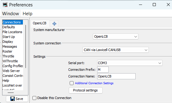 Configure a new connection by applying the following parameters:
-
System Manufacturer: OpenLCB -
System Connection:
Adapter System Connection CANable 2.0 Adapter CAN via MERG CAN-RS or CAN-USB (Lawicel) RR-CirKits LCC-Buffer-USB Adapter Serial CAN (GridConnect) Bluetooth Connection Serial CAN (GridConnect) -
Settings:These setting specify the LCC Node Hub for JMRI to connect to. A Hub is typically an LCC Node was previously configured to use Wi-Fi as a bridge between the Wi-Fi and the CAN Network.
Serial Port: COMx(Identify this as the Windows-assigned port upon connecting the USB-CAN device)Connection Prefix: M(default setting)Connection Name:[Your chosen name]
-
-
Finalize your settings by clicking the
Savebutton located at the bottom-right corner of the Preferences-Connections window. -
Reset JMRI DecoderPro
JMRI CDI Tool (Wi-Fi)
The Wi-Fi Connection option lets JMRI talk to your LCC Nodes over a wireless LAN—no USB-CAN dongle required. To use it you’ll need:
- An ESP32-based LCC Fusion Node running the “LCC Node Hub” firmware (preconfigured to start Wi-Fi).
- A Wi-Fi network that both your computer/RPi and the Node Hub can join.
Note: The LCC Fusion Desktop CDI Configuration Tool does not support Wi-Fi CAN access—you must use JMRI for Wi-Fi. For truly wireless, local CAN access on your PC use the Bluetooth adapter instead.
flowchart LR
  subgraph Host["Computer or Raspberry Pi"]
    jmri["JMRI: Configure Nodes Tool <br>(CAN via GridConnect <br>Network Interface)"]
  end
  nodeHub["LCC Node <br>(Hub Mode + Uplink Mode)"]
  nodeHub1["LCC Node"]
  nodeHub2["LCC Node <br>(Uplink Mode)"]
  jmri --> |"Wi-Fi CAN Network <br>"|nodeHub --> |"Wi-Fi CAN Network"|nodeHub2
  nodeHub1 <--> |"Wi-Fi CAN Network"|nodeHub
JMRI Wi-Fi Connection Configuration
Configure JMRI to treat the Node Hub as a GridConnect TCP interface:
- Start DecoderPro or JMRI.
- Edit → Preferences → Connections.
- System manufacturer:
OpenLCB - System connection:
CAN via GridConnect Network Interface - IP address / Hostname: the Node Hub’s Wi-Fi IP (e.g.
192.168.1.53) or mDNS name (e.g.esp32_NodeID.local) - TCP/UDP Port:
12021(must match the hub’s listener port) - Connection protocol:
OpenLCB - Connection Prefix:
M2(or your chosen prefix) - Connection Name: any descriptive label (e.g.
WiFi_CAN) - Save and Restart JMRI’s connection.
LCC Node Wi-Fi Configuration (Hub Mode)
Use any wired CDI tool (JMRI or Desktop) to turn your Node into a Wi-Fi Hub:
-
Flash the ESP32 with the LCC Node Hub firmware version.
-
Power on and connect via USB-CAN or CANable.
-
Select the node in your CDI editor (View → LCC Nodes).
-
Open Communication Configuration → Wi-Fi Communications → Hub Configuration.
-
(Optional) If running on battery, set Wi-Fi Power Savings Mode →
Yes. -
Set Enable Hub Mode →
Yes. -
Confirm Hub Listener Port →
12021(must match JMRI). -
Set mDNS Service →
_openlcb-can._tcp. - Click Save, then Restart Node.
After reboot, your Node Hub will advertise its TCP listener. The serial monitor will display its Wi-Fi IP and mDNS name—use that in your JMRI connection.
LCC Node Wi-Fi Configuration (Uplink Mode)
If you need a second LCC Node to act as a repeater or uplink to another Wi-Fi hub, use the Node Uplink Configuration group to enter that other hub’s IP and port, then restart. Both hubs must see each other on the same network.
Once both JMRI and the Node Hub are configured, you can edit CDI profiles over Wi-Fi just as if you were connected via a USB-CAN interface.
Using JMRI “Configure Nodes” Tool
- Click on OpenLCB_CAN in the top toolbar
- Select Configure Nodes
- OpenLCB Network Tree dialog window opens
- Click on twisty for the LCC Node to be configured
- Select Open Configuration dialog
- New window opens showing the CDI for the LCC Node.
- Each CDI configuration segment is shown with a title and a twisty to open
- Click on twisty to open and show the CDI
Remote Console Access
VNC over Wi-Fi
If you’ve installed the LCC Fusion Desktop Tool or JMRI on a Raspberry Pi with the CAN-RPI Card, you can connect to it wirelessly over your Wi-Fi network using a VNC client. This lets you run both CDI configuration tools on the Pi’s desktop from any computer on the same LAN.
flowchart LR
  CT["CDI Configuration Tools"]
  VC["VNC Client (Windows)"]
  RPi["Raspberry Pi"]
  CAN["CAN Network Adapter"]
  Node["LCC Node"]

  CT --> |"Viewing"| VC --> |"Wi-Fi"| RPi --> CAN --> Node
RPi Configuration
-
Join your Wi-Fi network
Edit/etc/wpa_supplicant/wpa_supplicant.conf(or use the Raspberry Pi Configuration tool in Desktop):sudo raspi-config -
Enter Wi-Fi Credentials
- → Network Options → Wi-Fi → enter SSID and passphrase
- Reboot if prompted.
-
Enable the VNC server
sudo raspi-config -
Enable VNC
-
→ Interface Options → VNC → Enable
Or from Desktop:
- Open Preferences → Raspberry Pi Configuration → Interfaces
- Turn VNC to Enabled
-
-
Set a VNC password (if required)
vncpasswd -
Find your Pi’s IP address
hostname -INote the Wi-Fi IP (e.g.
192.168.1.42). -
(Optional) Install additional desktop tools If you’re headless and want a GUI, install LXDE or another lightweight desktop:
sudo apt update
sudo apt install --no-install-recommends lxde-core lxterminal
Windows/Linux Configuration
- Install a VNC viewer
- RealVNC Viewer
- TigerVNC, TightVNC, etc.
- Connect to the Pi
- Launch your VNC client
- Enter
<Pi_IP>:1(e.g.192.168.1.42:1) or simply the IP (RealVNC auto-negotiates) - Authenticate with the password you set (or your Pi user credentials)
- Use the configuration tools
Once you see the Pi’s desktop, you can:
- Run JMRI: launch from the menu or command line (
python3 -m lcc_browser.guiif installed) - Run LCC Fusion Desktop: click its icon or run the
cdi-configuration-tool-desktopbinary - Run the Bluetooth tester: launch
cdi-bt-testif built
- Run JMRI: launch from the menu or command line (
Your PC now has full, wireless access to both CDI Configuration Tools as though you were sitting at the Pi’s HDMI-connected keyboard and display.
Verification & Troubleshooting Tips
After restarting JMRI Decoder Pro, verify the connection spanning from the computer, through the adapter, to the CAN network. This verification can be accomplished by choosing the OpenLCB tab from the top menu, followed by Configure Nodes. Every LCC Node within the CAN network should be visible in the Network Tree dialog.