DC Motor Driver Breakout Board Assembly Guide
Table of contents
Table of contents
Introduction
The DC Motor Driver Breakout Board, in combination with the LCC Fusion Node Card and Digital I/O Card, provides a versatile and robust solution for controlling up to two DC motors in your project. Designed with flexibility and ease of use in mind, this breakout board is perfect for a wide range of applications, whether you’re working on robotics, automation, or any other project requiring precise motor control.
Key Features:
- Dual Motor Control: The board supports two independent DC motors, allowing you to control each motor separately for complex maneuvers and operations.
- Voltage Selector: Easily switch between 5V and 12 VDC operation with an onboard selector, making this board adaptable to different motor voltage requirements.
- Layout Accessory Bus Input: This board integrates seamlessly with your existing layout accessory bus, simplifying the connection process and ensuring compatibility with your setup.
- Network Cable Connection: The board connects to your PWM Card via a standard network cable, ensuring reliable communication and easy integration into your system.
With these features, the DC Motor Driver Breakout Board offers a powerful yet straightforward way to control your DC motors, making it an essential component for any motor-driven project.
flowchart LR;
subgraph layout ["Train Layout"];
direction LR;
can["CAN Network"];
subgraph hub["Node Bus Hub"];
  n[["Node Card"]];
  pwm[["PWM Card"]];
end;
bb[["DC Motor<br>Breakout Board (2x)"]];
m(("DC Motors (2x)"));

can --> n;
n --> pwm;
pwm --> bb;
bb --> m;
end;
classDef lSalmonStyle fill:#FFA07A,stroke:#333,stroke-width:2px,font-size:20px;
class bb lSalmonStyle;
classDef lightGrayStyle fill:#d3d3d3,stroke:#333,stroke-width:2px,font-size:24px;
class layout lightGrayStyle;
System Overview:
The DC Motor Driver Breakout Board integrates with the LCC Fusion Node Card and PWM Card to provide robust control over up to two independent DC motors. This setup allows for precise manipulation of motor speed, direction, and power, making it ideal for a variety of motor-driven applications such as model train automation, robotics, and other automated systems.
Diagram Overview:
The following diagram illustrates the flow of signals and power within the DC Motor Driver Breakout Board system:
flowchart LR;
can["CAN Network"];
subgraph layout ["Train Layout"];
  direction LR;
  subgraph hub["Node Bus Hub"];
    n["Node Card"];
    pwm["PWM Card"];
  end;
  bb[DC Motor<br>Breakout Board];

  can --> |"LCC Event <br/> (on/off/speed)"| n;
  n --> |"PWM Signal <br/> (speed, direction)"| pwm;
  pwm --> |"PWM Signal <br/> (speed, direction)"| bb;
  bb --> |"Motor Control <br/>(power, speed, direction)"| m("DC Motor <br/> (2x, 5V/12 VDC)");
  acc["ACC POWER"] --> bb;
end;
classDef lSalmonStyle fill:#FFA07A,stroke:#333,stroke-width:2px,font-size:24px;
class bb lSalmonStyle;
classDef lightGrayStyle fill:#d3d3d3,stroke:#333,stroke-width:2px,font-size:24px;
class layout lightGrayStyle;
Control Flow:
- LCC Event:
- The control process begins with an LCC Event sent over the CAN Network. This event may indicate commands such as turning the motors on or off, adjusting their speed, or changing their direction.
- Node Card:
- The Node Card receives the LCC Event and processes it, converting the event into corresponding PWM signals that represent the speed and direction of the motors.
- PWM Card:
- The PWM Card receives the PWM signals from the Node Card and generates the appropriate PWM output signals for motor control.
- These signals are sent to the DC Motor Driver Breakout Board via a network cable, ensuring reliable and seamless integration between the control system and the motors.
- DC Motor Driver Breakout Board:
- The DC Motor Driver Breakout Board receives the PWM signals from the PWM Card and directly controls the power, speed, and direction of up to two connected DC motors.
- The board also includes a voltage selector that allows the user to choose between 5 VDC and 12 VDC operation, depending on the motor’s power requirements.
- Motor Operation:
- The breakout board sends the adjusted power, speed, and direction signals to the connected DC motors via standard connections. The motors respond based on the received signals, executing precise movements such as starting, stopping, changing direction, or adjusting speed.
- Power Supply:
- The breakout board is powered by the layout accessory bus (ACC POWER), providing a stable power supply for both the motors and control circuitry.
This versatile setup allows for precise and independent control of two DC motors, with the ability to adapt the board to different motor voltages (5 VDC or 12 VDC) using the onboard voltage selector.
Assembly and Component Placement
This section combines both the component specifications and the assembly instructions to ensure a smooth assembly process. Below is a comprehensive list of components, their placement on the PCB, and orientation details to assist you during assembly.
High-Level Steps for Assembly:
- PCB for the card can be ordered from any PCB fabricator using these Gerber Files.
- Clean PCB with alcohol to remove residue. See Cleaning_PCB for details.
- See also: Soldering Tips
- PCB Components - listing of components used for PCB assembly
- PCB Parts - listing of parts used for PCB assembly
![]()
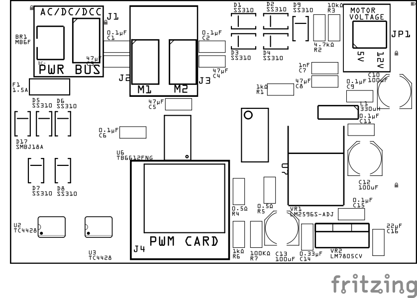
![]()
| Component Identifier | Count | Type | Value | Package | Purpose | Orientation |
|---|---|---|---|---|---|---|
| Bridge Rectifiers | ||||||
| BR1 | 1 | Bridge Rectifier | MB6F | SOP-4 | Converts DCC pulsating AC-like waveform into a DC-like pulsating waveform for current detection. | Position IC’s indent to PCB left edge) |
| Capacitors | ||||||
| C1, C2 | 2 | Capacitor-Ceramic | 0.1uF | 1206 X7R | Use to filter fast spikes | None |
| C3, C4 | 2 | Capacitor-Ceramic | 47uF | 1206 X7R | Use to handle bulk energy for the coil’s inrush | None |
| C5 | 1 | Capacitor-Ceramic | 0.1uF | 1206 X7R | Decoupler for TB6612FNG | None |
| C6 | 1 | Capacitor-Ceramic | 47uF | 1206 X7R | Use to smooth out switching noise for motors | None |
| C6 | 1 | Capacitor-Polymer Solid | 100µF | 6.3x5.8mm SMD | Smooths the TB6612FNG input voltage | Anode positioned toward PCB bottom edge |
| C7 | 1 | Capacitor-Ceramic | 1nF | 1206 X7R | Smooths the LM2596S-ADJ output voltage | None |
| C8 | 1 | Capacitor-Ceramic | 47µF | 1206 X7R | Smooths the LM2596S-ADJ output voltage | None |
| C9, C11 | 2 | Capacitor-Ceramic | 0.1µF | 1206 X7R | Smooths the LM2596S-ADJ input/output voltages | None |
| C10 | 1 | Capacitor-Polymer Solid | 100µF | 6.3x5.8mm SMD | Smooths the LM2596S-ADJ output voltage | Anode positioned toward PCB top edge |
| C12 | 1 | Capacitor-Polymer Solid | 100µF | 6.3x5.8mm SMD | Smooths the LM2596S-ADJ input voltage | Anode positioned toward PCB top edge |
| C13 | 1 | Capacitor-Polymer Solid | 100µF | 6.3x5.8mm SMD | Input filtering for the 5V voltage regulator | Anode positioned toward PCB top edge |
| C14 | 1 | Capacitor-Ceramic | 0.33µF | 1206 X7R | Used by 5V voltage regulator for input filtering | None |
| C15 | 1 | Capacitor-Ceramic | 0.1µF | 1206 X7R | Used by 5V voltage regulator for output filtering | None |
| C16 | 1 | Capacitor-Ceramic | 22µF | 1206 X7R | Used by 5V voltage regulator for output filtering | None |
| Diodes | ||||||
| D1 - D4 | 4 | Diode-Schottky | SS310 | SMA | Flyback voltage spike protection from motor | Cathode end has a white line and positioned towards PCB left edge |
| D5 - D9 | 5 | Diode-Schottky | SS310 | SMA | Required by LM2596S-ADJ for reverse voltage protection | Cathode end has a white line and positioned towards PCB top edge |
| D10, D11 | 2 | Diode-Schottky | SS310 | SMA | Required | Protects against reverse current |
| Fuses & Protection | ||||||
| F1 | 1 | Fuse-PTC Polymer | JK30, 1.5A, 16V (or more) | 5.1mm pitch, PTH | Protects from sustained overcurrent conditions | None |
| Connectors | ||||||
| J1, J2, J3 | 3 | Connectors | JST XH Socket (2P, 2.54mm) or 2P Spring Terminal | 2.54mm PTH | Connects to layout accessory bus (V+, GND) | Position connection outward |
| J4 | 1 | RJ45 Socket (8P8C, PTH) | 8P8C | PTH | Network cable (CAT5/6) connection from PWM Card | Fits only one way |
| Selectors | ||||||
| JP1 | 1 | Male Header | 2-Pin | PTH | Uses a Jumper Cap to select the voltage of the motor, 5 VDC, 12 VDC, INPUT. Selecting INPUTresults in ACC BUS voltage to be used for the motor. |
None |
| SH1 | 1 | Jumper Cap (Shunt) | 2.54mm | - | Use with JP1 | None |
| Inductors & Resistors | ||||||
| L1 | 1 | Inductor | 33µH | PTH | Used for 5V voltage regulation | None |
| R1 | 1 | Resistor | 1KΩ | PTH | Voltage divider (R1) for LM2596S-ADJ | None |
| R2 | 1 | Resistor | 4.7KΩ | PTH | Voltage divider (R2) for LM2596S-ADJ to adjust voltage regulator | None |
| R3 | 1 | Resistor | 10KΩ | PTH | Voltage divider (R2) for LM2596S-ADJ to adjust voltage regulator | None |
| R4, R5 | 2 | Resistor | 0.5Ω | 1206 SMD | Current limiting for TB6612FNG CS selectors to GND | None |
| ICs | ||||||
| U1 | 1 | Dual Full Bridge Driver | TB6612FNG | PTH | Provides dual full-bridge motor control | Fits only one way |
| U2, U3 | 2 | Mosfet Driver | TC4428 | SMD | Provides high-speed switching | Position indent (pin 1) towards PCB left edge |
| VR1 | 1 | Buck Converter | LM2596S-ADJ | SMD | 5V/12V buck converter for voltage regulation | Position indent (pin 1) towards PCB bottom edge |
| VR2 | 1 | Voltage Regulator | LM7805CV | TO-220 | Provides 5V to ICs | Position heat sink towards PCB top edge |
Tools Required
Safety Precautions
- See Safety Precautions.
Testing and Verification
Visual Inspection
- Initial Check: Examine the board for any obvious issues like missing components, solder bridges, or components that are misaligned or not fully seated.
- Solder Joint Inspection: Use a magnifying glass or a microscope to inspect solder joints. Look for cold solder joints, insufficient or excessive solder, or any shorts between pads.
Functional Testing
Troubleshooting
- See I2C Trouble Shooting.
Appendences
PCB Specifications
Specifications for the DC Motor Driver Breakout Board include:
| Characteristic | Value |
|---|---|
| Max DC Motors | 2 |
| Max Output per Motor | 2A |
| Output Voltage | 5V, 12 VDC1, INPUT2 |
| Min Input | 7V, 14 VDC2 |
| Max Input | 35 VDC |
- Output voltage selections include INPUT (voltage), 5V, and 12 VDC.
- When selecting INPUT, the output voltage is 2V less than the input voltage
- Input voltage must be at least 2V above output voltage.
How It Works
The combination of the TC4428 MOSFET driver and the TB6612FNG H-Bridge provides a powerful and flexible way to control the speed and direction of DC motors. Here’s a step-by-step explanation of how this setup works:
Motor Voltage Selection
A Jump Cap is used with the MOTOR VOLTAGE selector to select 5 VDC, or 12 VDC for the output to the motor. Based on the selection, a LM2596S-ADJ adjustable buck voltage converter is used to step down the PWR BUS voltage to either 5V or 12. Resistors are used to select the desired voltage regulator output.
Direction Control Using TC4428
The TC4428 MOSFET driver is used to set the direction of the DC motor by controlling the logic levels sent to the TB6612FNG H-Bridge. The DIRA pin on the TC4428 determines the motor’s direction:
- High (H): Sets the motor to move forward by making IN1=H and IN2=L on the TB6612FNG .
- Low (L): Reverses the motor direction by setting IN1=L and IN2=H on the TB6612FNG . This enables precise control over which direction the motor spins.
Speed Control Using PWM
The motor’s speed is controlled by a Pulse Width Modulation (PWM) signal sent to the ENA pin of the TB6612FNG .
- By varying the duty cycle of the PWM signal, you can adjust the speed of the motor.
- The higher the duty cycle, the faster the motor will spin, and vice versa.
Integration Between TC4428 and TB6612FNG
The TC4428 takes in a digital signal from a microcontroller or control logic and amplifies it to drive the inputs of the TB6612FNG H-Bridge.
- For Forward Movement: DIRA=High → IN1=H, IN2=L
- For Reverse Movement: DIRA=Low → IN1=L, IN2=H The TB6612FNG then drives the motor in the appropriate direction based on these signals.
Operational Modes: Forward: When the DIRA pin is high, and the PWM signal is active, the motor runs forward.
-
Reverse: When the DIRA pin is low, the motor runs in reverse.
-
Brake (Fast Stop): When both IN1 and IN2 are high or low while the PWM signal is active, the motor quickly stops.
-
Motor Stop: When the PWM signal (ENA) is low, the motor stops regardless of the state of IN1 and IN2.
Practical Application: This setup is useful for applications where precise control of motor speed and direction is needed, such as in robotics or automated systems. The integration between the TC4428 and TB6612FNG allows for both simple direction control and variable speed control using a single PWM signal.
Connections
| Components Designator | Connector Label | Connector Type | Connection Number | Function | Description |
|---|---|---|---|---|---|
| J1 | ACC BUS | JST XH, Spring Terminal | 1 | Vcc | Power supply from the layout accessory bus |
| J1 | ACC BUS | JST XH, Spring Terminal | 2 | GND | Ground connection |
| J2 | MOTORS 1-2 | JST XH, Spring Terminal | 1 (+) | Motor 1 (+) | Positive terminal of Motor 1 |
| J2 | MOTORS 1-2 | JST XH, Spring Terminal | 2 (-) | Motor 1 (-) | Negative terminal of Motor 1 |
| J3 | MOTORS 1-2 | JST XH, Spring Terminal | 1 (+) | Motor 2 (+) | Positive terminal of Motor 2 |
| J3 | MOTORS 1-2 | JST XH, Spring Terminal | 2 (-) | Motor 2 (-) | Negative terminal of Motor 2 |
| J4 | PWM CARD | RJ45 Socket | 1 | Motor Direction 1 | Controls the direction of Motor 1 (e.g., forward/reverse) |
| J4 | PWM CARD | RJ45 Socket | 2 | Motor Direction 2 | Controls the direction of Motor 2 (e.g., forward/reverse) |
| J4 | PWM CARD | RJ45 Socket | 3 | PWM (Enable) 1 | Controls the speed of Motor 1 via PWM signal (ENA pin on TB6612FNG) |
| J4 | PWM CARD | RJ45 Socket | 4 | PWM (Enable) 2 | Controls the speed of Motor 2 via PWM signal (ENB pin on TB6612FNG) |
| J4 | PWM CARD | RJ45 Socket | 5 | Current Sense 1 | Monitors the current through Motor 1 (SENSE A pin on TB6612FNG) |
| J4 | PWM CARD | RJ45 Socket | 6 | Current Sense 2 | Monitors the current through Motor 2 (SENSE B pin on TB6612FNG) |
| J4 | PWM CARD | RJ45 Socket | 7 | GND | Ground connection |
| J4 | PWM CARD | RJ45 Socket | 8 | Vcc | Power supply for logic and motor driver |
| JP1 | MOTOR VOLTAGE | 3-Pin Male Header | INPUT, 5V 12 VDC | 5V | Uses a Jumper Cap to select the voltage of the motor, 5 VDC, 12 VDC, INPUT. Selecting INPUTresults in ACC BUS voltage to be used for the motor. |
PCB Protection
The DC Motor Driver Breakout Board includes several key protection mechanisms to safeguard both the board itself and the connected components. Below is a detailed table outlining the protection provided against flyback voltage and reverse voltage, ensuring the longevity and reliability of your setup.
| Protected Component | Protection Component | Function | Specifications | Location |
|---|---|---|---|---|
| Entire Board (Relays, Devices, Voltage Regulator) | Crowbar Diode, Resettable Fuse | Crowbar Protection protects against reverse polarity by short-circuiting the power supply when connected backward, blowing the fuse to protect the circuit | Diode becomes forward-biased if reverse polarity occurs | Across the power supply input (ACC VDC+ to ACC GND) C VDC+ to ACC GND) |
| Accessory Power (ACC VDC+) | TVS Diode | Provides overvoltage protection to prevent damage from voltage spikes on the accessory bus | Voltage clamp at specified level (e.g., 12 VDC) | Across the ACC VDC+ and ACC GND power lines |
| TB6612FNG H-Bridge | Internal Flyback Diodes | Protects against inductive kickback from DC motors. | Integrated into the TB6612FNG H-Bridge. | Within the TB6612FNG H-Bridge IC. |
| TB6612FNG H-Bridge | SS310 Diode-Schottky | Protects against reverse voltage and reverse current. | Reverse Voltage: 40 VDC, Current: 2A. | On the DC Motor Driver PCB, across power lines. |
| LM2596-ADJ Regulator | Output Capacitor | Filters out high-frequency noise and transient voltage spikes from the output, ensuring stable 5V regulation. | Value: 680 µF Polymer Solid | Across the output (5 VDC) and GND |
| Voltage Regulators (LM7805) | Decoupling Capacitors | Filters noise, stabilizes output | Value: 0.33µF (input), 0.1µF (output) | Near regulator pins |
| IC’s | Decoupling Capacitor | Filters out high-frequency noise and transient voltage spikes from the power supply, ensuring stable voltage for the IC’s. | Value: 0.1 µF, 47uF ceramic | Across the Vcc input and GND |