Digital I/O Card & Breakout Board Installation Guide
Table of contents
Table of contents
Overview
The Digital I/O Breakout Board interfaces the Digital I/O Card with up to eight digital input or output devices. It supports a wide variety of devices such as sensors, buttons, LEDs, and small actuators used in model railroad automation and other low-power control applications.
The board is powered from one of the layout’s power bus (AC, DC, or DCC), rectified via an onboard bridge rectifier, and regulated to a stable 5 VDC supply for the devices and board circuitry.
What’s Needed
| Component | Purpose |
|---|---|
| Computer / RPI (3B+)1 | Runs JMRI for CAN communications with Node Card |
| Node Card & Power Supply | Interfaces with CAN network and cards (via Node Bus Hub) |
| Digital I/O Breakout Board | Interfaces digital I/O signals and power for digital I/O devices |
| Digital I/O Card | Interfaces with Node Card via serial communications and converts digital I/O to signals for the Digital I/O Breakout Board. |
| Digital I/O Devices (8 max) | Sensors, buttons, LEDs, relays, or actuators |
| Network Cable (CAT5/CAT6) | Connects Digital I/O Card to Digital I/O Breakout Board via RJ45 connector |
| 3-wire cables | Connect devices to breakout board JST XH connectors |
| Layout Power Bus (AC/DC/DCC) | Supplies breakout board power (<40 VDC, AC/DC/DCC) |
1) When using an RPi, you can simplify integration by using the RPi-CAN Card, which provides built-in CAN communication and connects directly to the LCC Fusion Node Bus—no extra wiring required. Otherwise, to run JMRI on a standalone Pi you will need:
- Raspberry Pi 3B+ (or newer): Runs JMRI for CAN communications. We recommend Steve Todd’s preconfigured JMRI image
- microSD card (8 GB or larger): Holds the JMRI OS image
- microSD card reader & imaging tool: For flashing the image to your card (e.g., balenaEtcher)
Connection Diagram
flowchart
  subgraph layout ["Train Layout"]
  	subgraph hub["Node Bus Hub"]
      nodeCard[["Node Card"]]
      ioCard[["Digital I/O Card"]]
    end
    jmri["JMRI Software<br>CDI Config Tool"]
    computer["Computer, or <br>Raspberry PI"]
    pwrSupply(("Power Supply"))
    breakout1["Digital I/O <br>Breakout Board"]
    breakout2["2nd Digital I/O <br>Breakout Board"]
    devices1(("Digital I/O Devices (8x)"))
    devices2(("Digital I/O Devices (8x)"))
    pwrbus(("PWR BUS <br>(AC/DC/DCC)"))
  end
  jmri -.- |"runs on"|computer <--> |"CAN Bus via<br>Network Cable"|nodeCard
  pwrSupply -.-> |"1+ A @ 40 v max via<br>2-wire"| nodeCard
  nodeCard <--> |"Digital I/O via<br>Node Bus"|ioCard
  ioCard <--> |"Digital I/O via<br>Network Cable → J10" |breakout1
  breakout1 <-.-> |"I/O via<br>2-wire → J1...J8"|devices1
  breakout1 <--> |"I/O via<br>Network Cable → J11" |breakout2
  breakout2 <-.-> |"Digital I/O via<br>2-wire →  J1...J8"|devices2
  pwrbus <--> |"14+ VDC via<br>2-wire Cable →  J9"|breakout1

  classDef lightBlueStyle fill:lightblue,stroke:#2c7a2c,stroke-width:2px,font-size:16px;
 	classDef lightGreenStyle fill:lightgreen,stroke:#333,stroke-width:2px,font-size:20px;
  class hub lightBlueStyle
  class ioCard,breakout1,breakout2 lightGreenStyle
Installation Steps
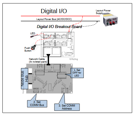 Connect the Digital I/O Breakout Board to the Digital I/O Card using a standard network cable (RJ45).
- Connect the layout Accessory Power Bus (AC, DC, or DCC) to the breakout board’s power input (J9).
- Connect up to eight digital devices to the breakout board’s 3-pin JST XH connectors:
- Pin 1: 5 VDC power (from board regulator, used for input device power)
- Pin 2: Signal line (digital input or output)
- Pin 3: Ground (common reference)
- Configure the Node Card firmware to set each I/O line as input or output as required by your application.
- Ensure wiring polarity and connections match device requirements — input devices expect power on Pin 1, output devices receive control signals on Pin 2.
Wiring Suggestions & Best Practices
-
Always connect device ground to Pin 3 (GND) for common reference.
-
For input devices (e.g., sensors, switches), connect device power to Pin 1 (5 VDC) and signal output to Pin 2 (Signal).
-
For output devices (e.g., LEDs, relays), device power is typically shared from the same 5 VDC rail; device control line connects to Pin 2, device ground to Pin 3.
-
Use shielded or twisted pair cables where possible to reduce noise on signal lines.
-
Avoid mixing input and output device connections on the same physical line without proper configuration to prevent damage.
-
Consult device datasheets for power and signal wiring requirements.
-
Ensure firm and secure connections to JST headers and network cables.
Device Type I/O Type Typical Wires Device Wire for 5V Pin Device Wire for SIG Pin Device Wire for GND Pin Notes Digital Sensor (e.g., proximity, IR) Input 3 VDC+ Signal (SIG) GND Sensor powered by 5 VDC; outputs digital signal Push Button / Switch Input 2 n/a Yes Yes Configure via CDI as Input with internal pull-up enabled LED (ON/OFF control) Output 2 n/a Anode Lead Cathode Lead Configure Digital I/O Card with 1kΩ current limiting resistor DC 5V Relay Module Output 3 VDC+ Signal (SIG) GND 5V Buzzer Output 2 n/a Yes Yes Simple ON/OFF control
Status Indicators
- Power LED: Illuminates when 5 VDC power is present and regulated on the breakout board.
Testing & Troubleshooting
- Cables & Connections
- Ensure the network cable between the Digital I/O Card and Breakout Board is fully seated and oriented correctly.
- Verify accessory bus voltage and polarity at the board’s power connector.
- Confirm device wiring matches the board pinouts (signal, VDC+, GND).
- Firmware & Diagnostics
- Use the LCC Configuration Monitor (JMRI), serial console, or other diagnostic tool to check that inputs register and outputs toggle as expected.
| Test | Check Point | Expected |
|---|---|---|
| Power LED | LED beside VR1 | LED is ON |
| PWR BUS Voltage | J9 VDC+ → GND | > 12 VDC (AC, DC, or DCC) |
| 5 VDC Regulator | J1–J4 VDC+ → GND | ≈ 5.0 VDC |
| Device Activation | Output lines 1–4 via J10 | Outputs switch on/off; inputs generate LCC Events |
| Daisy-Chain I/O | Lines 5–8 via J11 | Same results on lines 5–8 |
🧰 Troubleshooting Flow
Refer to the Output Device Flow and Input Device Flow diagrams for step-by-step guidance on isolating wiring, power, firmware, and device issues. If you reach a “Likely Bad Board” node, set the board aside for bench testing or builder support.
Output Device Text Flow
  flowchart TD
    subgraph "Output Device Test Flow"
      direction LR
      Connect-Power("Connect supply power to <br>PWR BUS connector (J5)")
      Connect-Card("Connect <br>Digital I/O Card")
      Connect-Device("Connect <br>output devices <br>(lamps, LEDs)<br>to connectors <br>(J1–J8)")
      Activate-Device("Activate input <br>device (LCC Event)")
      Activate-Input-Line("Bypass Digital <br>I/O Card: <br>Apply 5 V to each <br>input line (J6)")

      LED-Q{"Is the Power LED ON?"}
      PWR-Q{"Measure input at PWR BUS (J9).<br><br>Is voltage >14 V?"}
      Device-On-Q{"Do connected devices <br>turn ON correctly?"}
      Input-Test-Q{"Does the <br>corresponding <br>device turn ON?"}

      Success[[" Installation <br>Successful"]]

      Connect-Power --> LED-Q
      LED-Q -- "Yes, power LED is On" --> Connect-Card --> Connect-Device --> Activate-Device --> Device-On-Q
      LED-Q -- "No, power LED is Off" --> PWR-Q
      PWR-Q -- "Yes, valid input power" --> Bad-Board
      PWR-Q -- "No, invalid input power" --> Fix-PWR

      Fix-PWR["Check layout <br>power wiring, <br>power supply <br>voltage"]
      Fix-CDI["Verify card is good. <br>Check cards's <br>CDI configuration"]
      Fix-Device["Check device <br>wiring, polarity,<br>or replace device"]
      Bad-Board["Likely bad <br>Digital I/O<br>Breakout Board <br><br>Contact builder"]


      Device-On-Q -- "Yes, device working" --> Success
      Device-On-Q -- "No, device not working" -->   Activate-Input-Line --> Input-Test-Q
      Input-Test-Q -- "Yes, device works without <br>Output Card" --> Fix-CDI
      Input-Test-Q -- "No, device not working" -->  Bad-Board
    end

    %% Color styles
    classDef question fill:#d3d3d3,stroke:#333,stroke-width:2px,font-size:16px;
    classDef error fill:#FFA07A,stroke:#333,stroke-width:2px,font-size:16px;
    classDef success fill:#c6f6c6,stroke:#2c7a2c,stroke-width:2px,font-size:16px;
    classDef action fill:lightblue,stroke:#2c7a2c,stroke-width:2px,font-size:16px;

    class LED-Q,PWR-Q,Relay-Click-Q,Input-Test-Q,Device-On-Q question;
    class Fix-PWR,Fix-CDI,Fix-Device,Bad-Board error;
    class Connect-Power,Connect-Card,Connect-Device,Activate-Device,Activate-Input-Line action;
    class Success success;
Input Device Test Flow
flowchart TD
  subgraph "Input Device Test Flow"
    direction LR
    Connect-Power("Connect supply power to <br>PWR BUS connector (J5)")
    Connect-Card("Connect <br>Digital I/O Card")
    Connect-Device("Connect <br>input devices <br>(buttons, sensors)<br>to connectors <br>(J1–J8)")
    Activate-Device("Activate input <br>device")

    LED-Q{"Is the Power LED ON?"}
    PWR-Q{"Measure voltage <br>at PWR BUS (J9):<br><br>Is voltage >14 V?"}
    IOCard-Detect-Q{"Is input device detected <br>(CDI Event, <br>Card I/O line low)?"}
    Simulated-Input-Q{"Temporarily short <br>connector pins 1/2 <br>(J1-J8):<br><br>Does the <br>Digital I/O Card <br>detect the <br>input change?"}

    Fix-PWR["Check layout <br>power wiring, <br>power supply <br>voltage"]
    Fix-CDI["Check Digital I/O <br>Card CDI <br>config information"]
    Fix-Device["Bad input device: <br>Check device wiring, <br>polarity, and operation"]
    Bad-Board["Likely bad<br>Digital I/O Breakout Board<br><br>Contact builder"]

    Success[" Input Device<br>Detection Verified"]

    Connect-Power --> LED-Q
    LED-Q -- "Yes, power LED is On" --> Connect-Card --> Connect-Device --> Activate-Device --> IOCard-Detect-Q
    LED-Q -- "No, power LED is Off" --> PWR-Q
    PWR-Q -- "Yes, valid input power" --> Bad-Board
    PWR-Q -- "No, invalid input power" --> Fix-PWR

    IOCard-Detect-Q -- "Yes, device detected" --> Success
    IOCard-Detect-Q -- "No, device not detected" --> Simulated-Input-Q
    Simulated-Input-Q -- "Yes, simulated input succesful" --> Fix-Device
    Simulated-Input-Q -- "No, simulated input not detected" --> Fix-CDI
    Fix-CDI --> Bad-Board
  end
    %% Color styles
  classDef question fill:#d3d3d3,stroke:#333,stroke-width:2px,font-size:16px;
  classDef error fill:#FFA07A,stroke:#333,stroke-width:2px,font-size:16px;
  classDef success fill:#c6f6c6,stroke:#2c7a2c,stroke-width:2px,font-size:16px;
  classDef action fill:lightblue,stroke:#2c7a2c,stroke-width:2px,font-size:16px;

  class LED-Q,PWR-Q,Input-Wired-Q,IOCard-Detect-Q,Simulated-Input-Q question;
  class Fix-PWR,Fix-CDI,Fix-Device,Bad-Board error;
  class Connect-Power,Connect-Card,Connect-Device,Activate-Device action;
  class Success success;
Safety Notes
- Disconnect power before making or changing device connections.
- Do not exceed device current limits; max current is limited by the 5 VDC regulator and wiring.
- Use appropriate fusing on the accessory power bus to prevent damage.
