Hardware Assembly Guides
Table of contents
Table of contents
Introduction
The LCC Fusion Project hardware consists of PCBs that need to be built. Each PCB assembly guide provides the necessary information for obtaining the parts needed and steps for building the PCB.
Building PCBs consists of the following steps:
- Ordering the PCB from a PCB fabricator using the provided PCB design files called Gerber files. A Gerber file is a zip file containing the necessary details to create the specific PCB. JLCPCB is one of several PCB fabricators available. When ordering a PCB, consider ordering a stencil for applying solder paste.
- Ordering the PCB components from electronic sources such as AliExpress. The specific type and quantity of components required for each PCB are provided in the assembly guides.
- Assembling the PCB is performed by soldering components to the PCB while following the steps and guidelines provided in the PCB assembly guides.
- Testing the PCB is performed in a series of steps as outlined below and within each of the assembly guides.
For detailed information on design best practices and considerations, please see the PCB Design Guidelines section of our documentation.
PCB Build Sequence
The following is a recommended order in which to build the PCBs.
- Node Bus Hub is required for providing power and communications between a Power-CAN Card and other cards and breakout boards. Power includes 3V3, 5V, and 12+V. Communications includes CAN, DCC, and (2) I2C serial buses.
- Power-CAN Card is required for providing both power and communications for the LCC Fusion cards and breakout boards. After building this card, insert this card into the Node Bus Hub to provide power and communications with other cards and breakout boards.
- Quad-Node Card is required to run LCC Node firmware which communicates with the I/O cards and devices. This card can run from 1 to 4 independent LCC Nodes by installing up to 4 SuperMini ESP32-S3 boards. The Quad-Node Card must be inserted into a Node Bus Hub and powered with a Power-CAN Card. More than one LCC Node can share power and communications provided via the Node Bus Hub.
- Quad-Node Card is required to run the firmware for the LCC Node and to communicate with the I/O cards and devices. The Power-CAN Card must be used in conjunction with the Quad-Node Card to provide both power and CAN communications. Both cards should also be inserted into a Node Bus Hub.
Creating Layout Automation Solutions
Below is a summary of the many layout automation solutions available using the LCC Fusion Project PCBs (cards and breakout boards).
The table below lists the LCC Fusion Cards and LCC Fusion Breakout Boards to be added to the basic LCC Fusion Node Cluster consisting of a Node Bus Hub with either a Node Card, or a Power-CAN Card with one or more Quad-Node Card installed in the hub. Note that each Quad-Node Card can support up to 4 individual LCC Nodes by plugging in 1 to 4 SuperMini ESP32-S3 development boards.
Signal & Turnout Automation Example
For example, to control signaling and turnouts for a siding, one possible configuration consists of:
Node Card connected to a (computer) power supply to run LCC Fusion Project firmware
Node Bus Hub provides a hardware interconnect between LCC Fusion Project hardware cards
BOD Card + Block Breakout Board provides detection of trains in track blocks
PWM Card + Signal Mast Breakout Board provide control of the signal mast heads and aspects
Turnout Card + Turnout Stall Motor Breakout Board provides control of a turnout motor with point set indicators
Notes:
- Node, BOD, PWM, Turnout cards are inserted into the hub for power and communications (no wiring)
- Block, Signal Mast, and Turnout breakout boards positioned near their devices under the layout, connected to their corresponding card via network cables, and wired directly to the devices using the provided connectors.
flowchart TD
power🔌Computer Power Supply
subgraph cluster["LCC Fusion Node Cluster"]
  subgraph hub [" "]
  	hubtitle("Cards<br>(plugged in <br>Node Bus Hub)📦📦📦📦")
  	hubbb["LCC Fusion Hub"]
    nodec>"🧩Node Card"]
    bodc>"🧩BOD Card"]
    pwmc>"🧩🚦PWM Card"]
    turnoutc>"🧩Turnout Card"]
  end
  subgraph blayout [" "]
    blayouttitle("Breakout Boards<br>(⬇️under layout, near devices)")
  	blockbb[["📶Block Breakout Board"]]
  	pwmbb[["🔆Signal Mast Breakout Board"]]
    turnoutbb[["🔀Turnout Stall Motor<br>Breakout Board"]]
  end
  end
  subgraph tlayout [" "]
  	tlayoutTitle("Devices<br>(⬆️top of layout)")
    turnout️🔀Turnout Switch Machine
    lamps(("🚦💡Signal Lamps"))
    block[/"🚆Track Blocks"/]
  end
  power --> nodec
  nodec -.- |"📦 Card Slot 1"|hubbb
  hubbb -.- |"📦 Card Slot 4"|bodc
  hubbb -.- |"📦 Card Slot 3"| pwmc
  hubbb -.- |"📦 Card Slot 2"| turnoutc
  bodc --- |"🔗Network Cable"| blockbb
  pwmc --- |"🔗Network Cable"| pwmbb
  turnoutc --- |"🔗Network Cable"| turnoutbb
  blockbb  -.- |"⚡Rail Drop Wires"| block
  pwmbb -.- |"⚡Lamp Wires"| lamps
  turnoutbb -.-> |"⚡Motor & Frog Wires"| turnout

classDef lSalmonStyle fill:#FFA07A,stroke:#333,stroke-width:1px,font-size:20px;
class hub lSalmonStyle;
classDef lightGrayStyle fill:#d3d3d3,stroke:#333,stroke-width:1px,font-size:20px;
class tlayout lightGrayStyle;
class blayout lightGrayStyle;
classDef lightblueStyle fill:lightblue,stroke:#333,stroke-width:1px,font-size:16px;
class cluster lightblueStyle;
Implementing Automation Solutions
The following table outlines various automation solutions available with the LCC Fusion Project, highlighting the required Card and Breakout Board assemblies (if any), along with a brief description of each feature. These solutions extend the capabilities of an LCC Node Cluster, enabling enhanced diagnostics, configuration, and control functions such as wireless access, messaging, and more.
Configuration & Administration
| Solution | Card Assembly Guides | Breakout Board Assembly Guides | Description |
|---|---|---|---|
| Bluetooth LCC Configuration Bridge | None | None | Provides a Bluetooth-to-CAN bridge for wireless LCC configuration tools on Windows and Linux; only one bridge per Node Cluster is required. |
| Bluetooth Admin Console Access | None | None | Enables Bluetooth serial-terminal applications to connect to LCC Nodes and view admin console messages. |
Power & Utility
| Solution | Card Assembly Guides | Breakout Board Assembly Guides | Description |
|---|---|---|---|
| Battery-Backup Support | Battery Card | None | Provides uninterrupted power to an LCC Fusion Node cluster using the Battery Card. |
| Power Monitoring | Node CardPower-CAN Card | None | Monitors current (A), voltage (V), and power (W) on the supply input and 3.3 VDC, 5 VDC, and 12 VDC outputs; displays readings on a 0.96″ OLED and via the serial console. |
I/O Interfaces
| Solution | Card Assembly Guides | Breakout Board Assembly Guides | Description |
|---|---|---|---|
| Generic Device I/O Interface | None | None | Provides up to 8 flexible I/O lines supporting digital I/O, PWM, ADC, and touch; generates and responds to LCC Events accordingly. PWM is used to control motors and LED lighting effects. LCC Events can be produced using digital input, ADC to monitor sensors, or using touch of a finger to a wire/contact point. |
Detection Solutions
| Solution | Card Assembly Guides | Breakout Board Assembly Guides | Description |
|---|---|---|---|
| Analog Sensor Input | Node Card | Node Analog Sensor Breakout Board | Monitors up to 8 two-wire and three-wire analog sensors (LDR, FSR, potentiometer, proximity); generates LCC Events on threshold crossings. |
| Digital Sensor Input | Node Card Sensor Card |
Digital Sensor Breakout Board | Monitors up to 16 two-wire and three-wire digital sensors (Hall, touch, proximity, rotary encoder); generates LCC Events on state changes. |
| Low-Voltage & Short-Circuit Detection | BLVD Card | BLVD Breakout Board | Detects track voltage drops below 12 VDC or short-circuit conditions across up to 8 blocks; generates LCC Events per block. |
| NFC/RFID Tag Detection | NFC Tag Reader Card | NFC Tag Reader Breakout Board | Detects NFC/RFID tags on passing trains via an under-track antenna; generates LCC Events when tags are read. |
| Push-Button Input | Button Card | Digital I/O Breakout Board | Detects button presses on up to 16 inputs using Schmitt-trigger debouncing; generates LCC Events on state changes. |
| Track Occupancy Detection (Current Sense) | BOD Card | Block Breakout Board | Detects train presence in up to 8 blocks via current sensing; generates LCC Events per block. |
| Train Position Detection (IR) Sense | POD Card | POD Breakout Board | Uses paired under-track and track-side IR sensors to detect train position across up to 8 lines; generates LCC Events accordingly. |
| Ultrasonic Object Detection | UOD Card | UOD Breakout Board | Detects objects within a configurable range using ultrasonic sensors; generates LCC Events on detection. |
Control Solutions
| Solution | Card Assembly Guides | Breakout Board Assembly Guides | Description |
|---|---|---|---|
| Audio Annunciation System | Audio Card | None | Converts user configured text messages and .wav files to speech output through the Audio Card for announcements from LCC Events. For example, announce status after moving turnout points, or an announcement when a train is detected approaching a train station. |
| Audio Playback Control | Sound Card | None | Triggered by LCC Events, starts and stops MP3 playback on up to 5 independent players on the Sound Card from LCC Events. |
| DC Motor Control | PWM Card | DC Motor Driver Breakout Board | Controls DC motors by setting speed and direction via PWM signals generated from LCC Events. |
| LED Output Control | Digital I/O Card Output Card |
Digital I/O Breakout Board | Drives up to 16 digital output lines at 5 VDC or 12 VDC (≤ 500 mA each) via LCC Events for LED indicators. |
| NeoPixel Strip Control | Node Card | NeoPixel Breakout Board | Controls up to 8 NeoPixel LED strips via addressable outputs triggered by LCC Events. |
| Relay Device Switching | Node Card Digital I/O Card Output Card |
Relay Breakout Board | Operates up to 4 relays (≤ 1 A at 110 VAC/DC) for switching external devices via LCC Events. |
| Rule-Based Signal Control | BOD Card PWM Card |
Signal Masts Breakout Board Signal Head Breakout Boards |
Automates signal aspects based on block detection and user-defined rules; drives lamps accordingly. |
| Servo Motor Control | PWM Card | Servo Motor Driver Breakout Board | Controls standard servos (e.g., SG90) by setting position via PWM signals from LCC Events. |
| Stepper Motor Control | PWM Card | Stepper Motor Driver Breakout Board | Controls stepper motors by specifying speed, direction, and stop via LCC Events. |
| Turnout (Points) Control | Turnout Card | 1. Turnout Stall Motor Switch Machine Breakout Board 2. Turnout Coils Switch Machine Breakout Board 3. Turnout Servo Stall Motor Switch Machine Breakout Board 4. Turnout Slow Motion Switch Machine Breakout Board |
Throws and closes point sets via LCC Events; generates completion Events after movement. |
PCB Testing Sequence
PCB Assembly Guides: From Start to Finish
Below, you’ll find links to specific guides for each LCC Fusion Cards. included in the LCC Fusion Project. These guides are tailored to the unique aspects of assembling each type of PCB, yet they all follow the same fundamental principles outlined in our sequence diagram. This consistency ensures that, no matter which PCB you’re working on, the process remains familiar and straightforward.
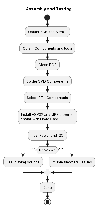 Sequence of Activities:
- Preparation: Gathering the necessary tools and components.
- Soldering: Step-by-step instructions for soldering components onto the PCB.
- Testing: Guidelines for testing the PCB to ensure functionality.
- Integration: Advice on integrating the assembled PCB into your model railroad layout.
- Troubleshooting: Common issues and how to resolve them.
Assembly Guides
The assembly guides are organized into the following two categories:
- Card Assembly Guides provide the builder with details on how to assemble the LCC Fusion Cards for both the LCC Fusion Node Card and the LCC Fusion Cards.
- Breakout Boards Assembly Guides provide the builder with details on how to assemble the LCC Fusion Project cards for both the LCC Fusion Node Card and the LCC Fusion Cards.
Additional Materials:
Supplies
- PCB Components - listing of components used for PCB assembly
- PCB Parts - listing of parts used for PCB assembly