Subjects: Assembly Guides , Automation , Hardware , Signaling , Train Detection
Use Cases: Automation Deployment , Node Cluster Setup , PCB Design & Assembly , Signaling Systems , Train Detection
Line Monitor Board Assembly Guide
Table of contents
Introduction
The Line Monitor Board is a diagnostic tool designed for use with the LCC Fusion system. It connects between any LCC Fusion I/O Card and its corresponding Breakout Board using standard RJ45 cables. Its purpose is to help users verify proper wiring, signal activity, and voltage levels on all 8 lines of the system’s internal cable connections.
The board features visual LED indicators that show:
- Power Status (L2): Whether power is present on the line (e.g., 5V, 12V, Track V)
- Ground Status (L1): Whether a valid ground reference is present
- Line Activity (L1–L8): One LED per line to indicate signal status — logic high/low, PWM, analog, or audio-frequency activity depending on the card type
This makes it easy to:
- Confirm that a breakout board is correctly connected
- Detect missing or incorrect ground and power lines
- Visually identify whether each line is idle, active, or behaving abnormally
- Troubleshoot cable issues, reversed cards, or firmware errors
The Line Monitor Board is especially useful during layout debugging, bench testing, or field installation. It supports all standard LCC Fusion cards, including sensor, turnout, audio, PWM, and detection cards.
By observing LED patterns — such as steady on, blinking, or off — users can interpret the health and activity of the connection at a glance. The board may also include an onboard ESP32-S3 (SuperMini) to provide smarter signal interpretation and LED behavior for advanced monitoring scenarios.
Line Monitor LED Planning Table
| Card Type | Active State | PWR LED | L1–L8 LEDs | L1 | L2 | L3 | L4 | L5 | L6 | L7 | L8 |
|---|---|---|---|---|---|---|---|---|---|---|---|
| Sensor Card | LOW | ✅ | ✅ | GND | 5V | 5V | 5V | 5V | 5V | 5V | 5V |
| Node I/O (RJ45 Connector) | LOW | ✅ | ✅ | GND | 5V | 3.3V/ADC | 3.3V/ADC | 3.3V/ADC | 3.3V/ADC | 3.3V/ADC | 3.3V/ADC |
| UOD Card | LOW | ✅ | ✅ | GND | 5V | 3.3V | 3.3V | 3.3V | 3.3V | 3.3V | 3.3V |
| Button Card | LOW | X | ✅ | 5V | 5V | 5V | 5V | 5V | 5V | 5V | 5V, GND |
| I/O Card | HIGH | X | ✅ | 5V | 5V | 5V | 5V | 5V | 5V | 5V | 5V, GND |
| Turnout Card | HIGH (PWM) | X | ✅ | 9V/12V | 9V/12V | 5V | 5V | 9V/12V | 9V/12V | 5V | 5V |
| PWM Card | HIGH (PWM) | X | ✅ | 5V/12V PWM | 5V/12V PWM | 5V/12V PWM | 5V/12V PWM | 5V/12V PWM | 5V/12V PWM | 5V/12V PWM | 5V/12V PWM, GND |
| Output Card | HIGH | X | ✅ | 9V/12V | 9V/12V | 9V/12V | 9V/12V | 9V/12V | 9V/12V | 9V/12V | 9V/12V, GND |
| BOD Card | VARIES | X | ✅ | Track V | Track V | Track V | Track V | Track V | Track V | Track V | Track V |
| BLVD Card | VARIES | X | ✅ | Track V | Track V | Track V | Track V | Track V | Track V | Track V | Track V |
| BRD Card | VARIES | X | ✅ | Track V | Track V | Track V | Track V | Track V | Track V | Track V | Track V |
| POD Card | LOW | X | ✅ | 5V | 5V | 5V | 5V | 5V | 5V | 5V | 5V, |
| Sound Card | VARIES (AC) | X | ✅ | Audio (AC) | Audio (AC) | Audio (AC) | Audio (AC) | Audio (AC) | Audio (AC) | Audio (AC) | Audio (AC) |
| Audio Card | VARIES (AC) | X | ✅ | Audio (AC) | Audio (AC) | Audio (AC) | Audio (AC) | Audio (AC) | Audio (AC) | Audio (AC) | Audio (AC) |
- lcc_fusion_node_card - not defined
For other terms, please refer to the full Terminology Guide.
Assembly and Component Placement
This section combines both the component specifications and the assembly instructions to ensure a smooth assembly process. Below is a comprehensive list of components, their placement on the PCB, and orientation details to assist you during assembly.
High-Level Steps for Assembly:
- PCB for the card can be ordered from any PCB fabricator using these Gerber Files.
- Clean PCB with alcohol to remove residue. See Cleaning_PCB for details.
- See also: Soldering Tips
- PCB Components - listing of components used for PCB assembly
- PCB Parts - listing of parts used for PCB assembly
Below is a list of the PCB components used for this card (see diagram before reference):
- Use of 2-pin JST XH pre-wired plugs soldered to track rail drop wires makes for easy wiring and fast connect/disconnect.
- Use of 2-position Spring Terminals (2.54mm) allow for rail drop wires to be connected directly pulling back a spring lever. These connectors can be ordered as 2-Position or assembled into a set of 2-Positions.
- Make sure this track rail has isolators creating blocks, where each block is wired to one or more of BLVD Breakout Boards and a BLVD Card.
| Component Identifier | Count | Type | Value | Package | Purpose | Orientation |
|---|---|---|---|---|---|---|
| Connectors | ||||||
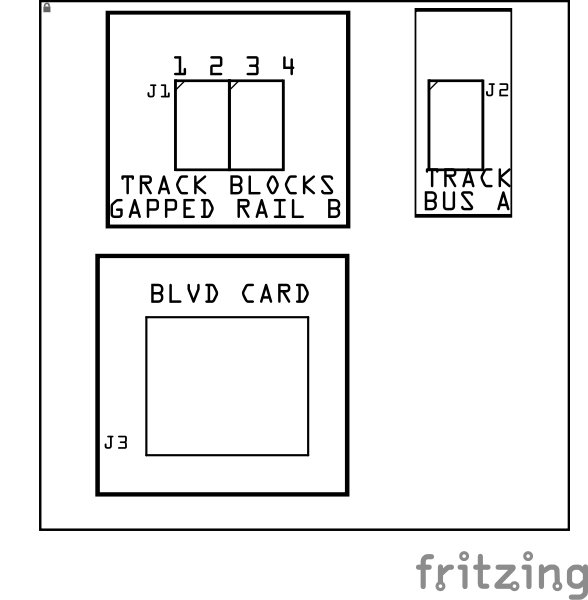
| J1 | 1 | JST XH Socket or 4-Position Spring Terminal Connector | 4P, 2.54mm | PTH, vertical or horizontal | Connectors to track Block Rails (isolated into block). | Position connection outward |
| J2 | 1 | JST XH Socket or 2-Position Spring Terminal Connector | 2P, 2.54mm | PTH, vertical or horizontal | Connector to Track Bus A (non-gapped Rail A). | Position connection outward |
| J3 | 1 | RJ45 Socket | 8P8C | PTH | Network cable (CAT5/6) connection from BLVD Card. | Fits only one way |
Tools Required
Safety Precautions
- See Safety Precautions.
Testing and Verification
Visual Inspection
- Initial Check: Examine the board for any obvious issues like missing components, solder bridges, or components that are misaligned or not fully seated.
- Solder Joint Inspection: Use a magnifying glass or a microscope to inspect solder joints. Look for cold solder joints, insufficient or excessive solder, or any shorts between pads.
- Use an Digital Multimeter (DMM) to test for continuity between:
- RJ45 socket pins (2, 4, 6, 8) and the 4 block connectors (J1, J2).
- RJ45 socket pins (1, 3, 5, 7) and the Track Bus connector (J3)
Functional Testing
Refer to BLVD Card for details on testing the BLVD Breakout Board with the BLVD Card.
Troubleshooting
- See I2C Trouble Shooting.
Appendences
Specifications
Specifications for the Block Breakout Board include:
| Characteristic | Value |
|---|---|
| Max Track Blocks | 4 |
| Max Track Voltage | 40V |
How It Works
For details, refer to the BLVD Card How it Works section.
Connections
The purpose of the BLVD Breakout Board and its connectors is to facilitate quick and easy connections between the BLVD Card and the track rails. For setups with multiple distant blocks, breakout boards can be daisy-chained together, or a network cable with a splitter can be used to provide multiple connections efficiently.
| Component Designator | Connector Label | Connector Type | Connection Number | Description |
|---|---|---|---|---|
| J1 | TRACK BLOCKS (GAPPED RAIL B) | JST XH, Spring Terminal | 1, 2, 3, 4 | Connection to insulated block rails |
| J2 | TRACK BUS A | JST XH, Spring Terminal | 1 | Connection to non-insulated rail |
| J3 | BLVD CARD | RJ45 Socket | 1/2, 3/4, 5/6, 7/8 | Each pin pair connects to blocks 1 thru 4. Cable to BLVD Card for low voltage detection caused by shorts or faulty connections. |