Node Card Configuration Guide
Table of contents
Table of contents
Introduction
LCC Fusion Node Card firmware Configuration for LCC Events
This part will detail the process for configuring the firmware to handle LCC events related to the LCC Fusion Node Card. Using the LCC Configuration Tool, it will outline steps to integrate the card with the LCC Fusion firmware, setting up LCC Event IDs to drive output devices. 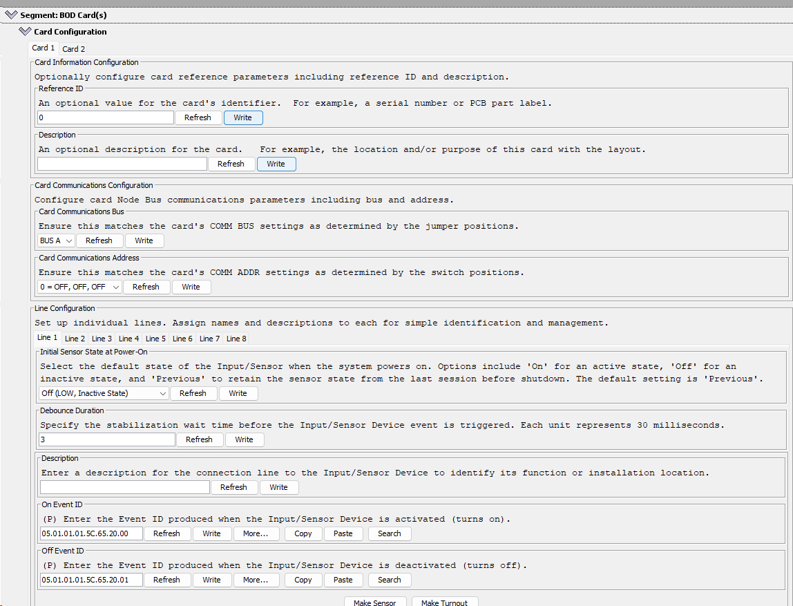
- Using the LCC Configuration Tool find the LCC Node and open the configuration.
- Scroll down to the LCC Fusion Node Card segment and click on the twistie to open the configuration dialog box for the card
- Select the tab for the specific line to be configured. Note that unconnected lines can be configured for future use.
- Make changes and click Write to save the change.
- After all changes are made, click Refresh to verify changes took affect.
Below are the card dialog configuration options for this card (refer to diagram on right):
After changing fields, click the Write button to save the changes.
Configuring LCC Fusion Node Card I/O Lines
The configuration interface dialog (see image on right) for a LCC Fusion Node Card, as presented in the JMRI Configuration Tool, includes several sections that allow for the customization and setup of the RJ45 I/O pins within a model railroad environment:
Here you can assign names and descriptions to individual I/O lines suppported by the LCC Fusion Node Card. Each line corresponds to one of the RJ45 lines for I/O.
-
Description:
- A field for providing a description for each line, which could detail the function or physical location of the Input/Sensor device connected to that line.
-
Initial Line State at Power-On:
- This setting determines the default state of the output line when the system is powered on. Options include ‘On’ for active, ‘Off’ for inactive, and ‘Previous’ to retain the state from before the system was last shut down.
-
Line Type and Corresponding Fields
-
UNUSEDUse when there is no device attached or being used.`` -
Digital Input,Digial Input-Pullup, andDigital Input-Pulldown-
Use to turn devices on/off using a digital signal (TTL). Devices include LEDs, relays, etc.
- Digital Input: No internal pull-up or pull-down resistor. The pin will be floating when not driven.
- Digital Input-Pullup: Enables the internal pull-up resistor, pulling the pin to a high state when not driven.
- Digital Input-Pulldown: Enables the internal pull-down resistor, pulling the pin to a low state when not driven.
-
-
PWM Output
PWM Output Level (%)The PWM output level from 0% to 100%). For an LED, this would be the % of brightness.
-
Touch Input
Touch Sensitivity (%)-
Values: 0% to 100% adjustment
-
Description: Adjusts how responsive the touch sensor is to touch events. Higher sensitivity means the sensor is more responsive to lighter touches.
-
-
ADC (Analog to Digital Converter) Input
Read analog values from sensors.
- Trigger Range
ACC Upper Range:The lower threshold value that will trigger an event when exceeded.ADC Lower Range:` The upper threshold value that will trigger an event when the reading goes below it.
- Trigger Range
-
Debounce Duration-
For Digital Input: This value sets the stabilization wait time before the Ievent is triggered to avoid false detections due to noise. The duration is in increments of 30 milliseconds.
-
For Output: N/A
-
-
OnEvent ID and OffEvent ID- Used for Digital Input, these fields are for entering the Event IDs that are produced when the line goes High (3.3 VDC) or Low (0 VDC).
- Used for Touch Input, these field are for entering the Event IDs that are produced when a touch pad goes low (touched).
- Used for ADC Input, these field are for entering the Event IDs that are produced when ADC input value is within the configured ADC range.
- Used for Digital Output, these field are for entering the Event IDs that set the output line High (3.3 VDC) or Low (0 VDC).
- Used for PWM Output, these field are for entering the Event IDs that set the PWM brightness at the configured level (brightness)
Setting ADC Thresholds
This section provides guidance on using the ADC example table to set lower and upper threshold limits for various sensors connected to the Node Card. These thresholds help define specific actions or alerts, such as indicating track occupancy, train proximity, or environment monitoring. With these examples, you can set custom threshold limits in your configuration to optimize how each sensor responds within your model railroad system.
How to Use the Table for Setting Threshold Limits
-
Identify the Sensor Type: Start by finding the sensor you’re working with in the table, such as a potentiometer, IR distance sensor, or current sensor.
-
Determine the Expected Output Range: Use the “Expected Output Range” column to understand the sensor’s voltage range. Each range corresponds to specific ADC values at 12-bit resolution, which you can monitor to set a response threshold.
- Configure Lower and Upper Thresholds:
- Lower Threshold: Use this to set a baseline or minimum detection point, typically around the lower end of the expected output range. For example, for an IR distance sensor used to detect proximity, you might set a lower threshold at 500 to detect objects further away.
- Upper Threshold: This sets the maximum detection point, which is useful for closer detection or higher intensity responses. For instance, to detect objects closer than 5 cm with an IR sensor, an upper threshold of 1240 would be appropriate.
- Example: For track occupancy detection using the ACS712 current sensor, you could set:
- Lower Threshold: 1800 to indicate a light load
- Upper Threshold: 2200 to indicate occupancy due to a train drawing current
Here’s a table for typical usage scenarios for an ADC input on a model railroad. It demonstrates example sensors, their expected output range, and how these map to ADC values for an ESP32 ADC.
Node Card’s ESP32 uses a 12-bit resolution for ADC, providing a value range of 0 to 4095
Sensor Type Expected Output Range ADC Range Typical Use Case Threshold Example Potentiometer 0V - 3.3 VDC 0 - 4095 Adjusting brightness of LEDs, controlling speed Set speed level threshold at 2048 (1.65 VDC) TMP36 Temperature Sensor ~0.5 VDC - ~2 VDC 620 - 2480 Monitoring ambient temperature Threshold at 930 (around 25°C, or 77°F) ACS712 Current Sensor 1.65 VDC ± 0.66 VDC 2048 ± 820 Track occupancy detection (detects current) Occupied threshold above 2200 (indicating load) Voltage Divider 0V - 3.3 VDC 0 - 4095 Detecting block occupancy Threshold around 1000 for moderate occupancy IR Distance Sensor (0-10cm) 0.4 VDC - 2V 500 - 2480 Train proximity detection Trigger threshold set at 1240 for 5 cm -