Node Card - Step-By-Step Assembly Guide
[TOC]
Before You Begin
Step 1. Review Configuration Options
Before soldering, determine which options you are building:
- Power input method(s)
- CAN bus connection type
- Node Bus Hub connection (local vs remote)
- I/O device support
- Indicators, buzzer, battery backup, SD card, display
Refer to the Assembly Configuration Options in the Node Card documentation.
Step 2. Gather Tools and Materials

Required Materials
- Node Card PCB and stencil
- PTH and SMD components for your selected configuration
- PCB standoffs (M3, ~11 mm) and nuts
SMD Assembly Tools
- Reflow oven (countertop, digital)
- Solder paste
- Solder paste applicator (syringe, container, or automatic dispenser)
- Paste scraper
- Push pins (for stencil alignment)
- Sticky pickup tool and/or fine tweezers
- Isopropyl alcohol and lint-free wipes
PTH Assembly Tools
- Soldering iron with fine tip
- Solder (PTH components)
Inspection and Handling
- Multimeter
- Magnification (loupe or microscope)
- Foam board or heat-resistant work surface
Step 3. Prepare the PCB
- Inspect the PCB for damage or contamination.
- Clean both sides with isopropyl alcohol.
SMD Assembly
Do not install through-hole components, the ESP32 module, or tall connectors at this stage.
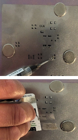
Step 4: Apply Solder Paste
-
Place the PCB flat on 1/4” foam board to support it during stencil work.
-
Position the stencil on top of the PCB and align it using the tooling holes (1.0 mm hole along the top edge and along the bottom edge).
-
Insert push pins through the tooling holes to hold the stencil aligned and in place.
-
Apply solder paste across the stencil openings, then scrape off the excess so paste remains only in the pads.
-
Remove the stencil carefully, lifting straight up to avoid smearing paste.
-
Install the standoffs and nuts now at the four mounting holes using nuts, leaving the board supported and level. This keeps the through-hole leads clear of the surface during reflow
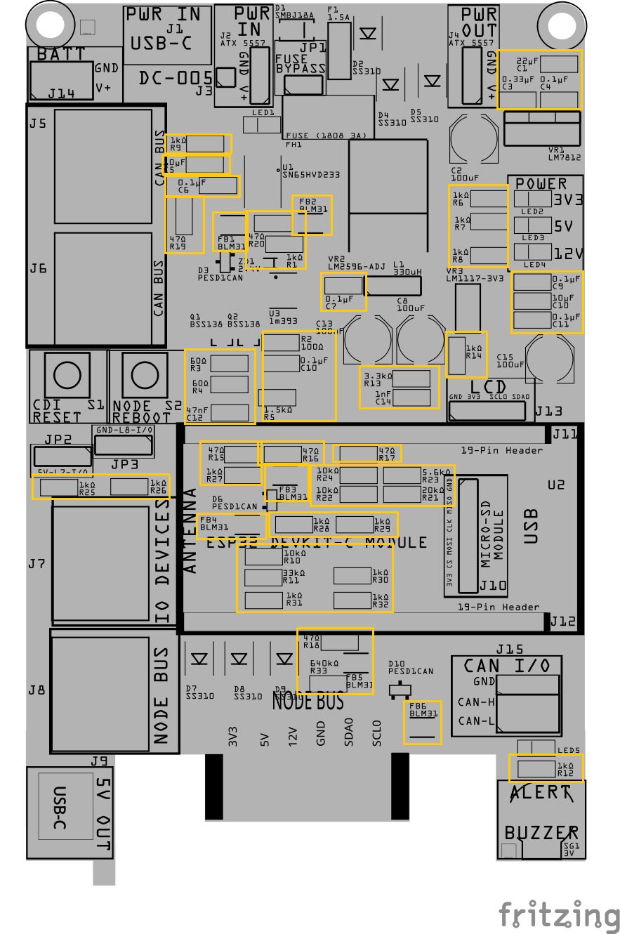
Step 5: Install Small SMD Components (No Orientation Required)
-
Place the small surface-mount components that do not have a direction or polarity.
This includes:
- All resistors (Rx)
- Small ceramic capacitors (Cx)
- Ferrite beads (FBx)
These parts can be placed in either direction, so orientation is not critical.
Step 6: Install Small SMD Components (That Have a Direction)
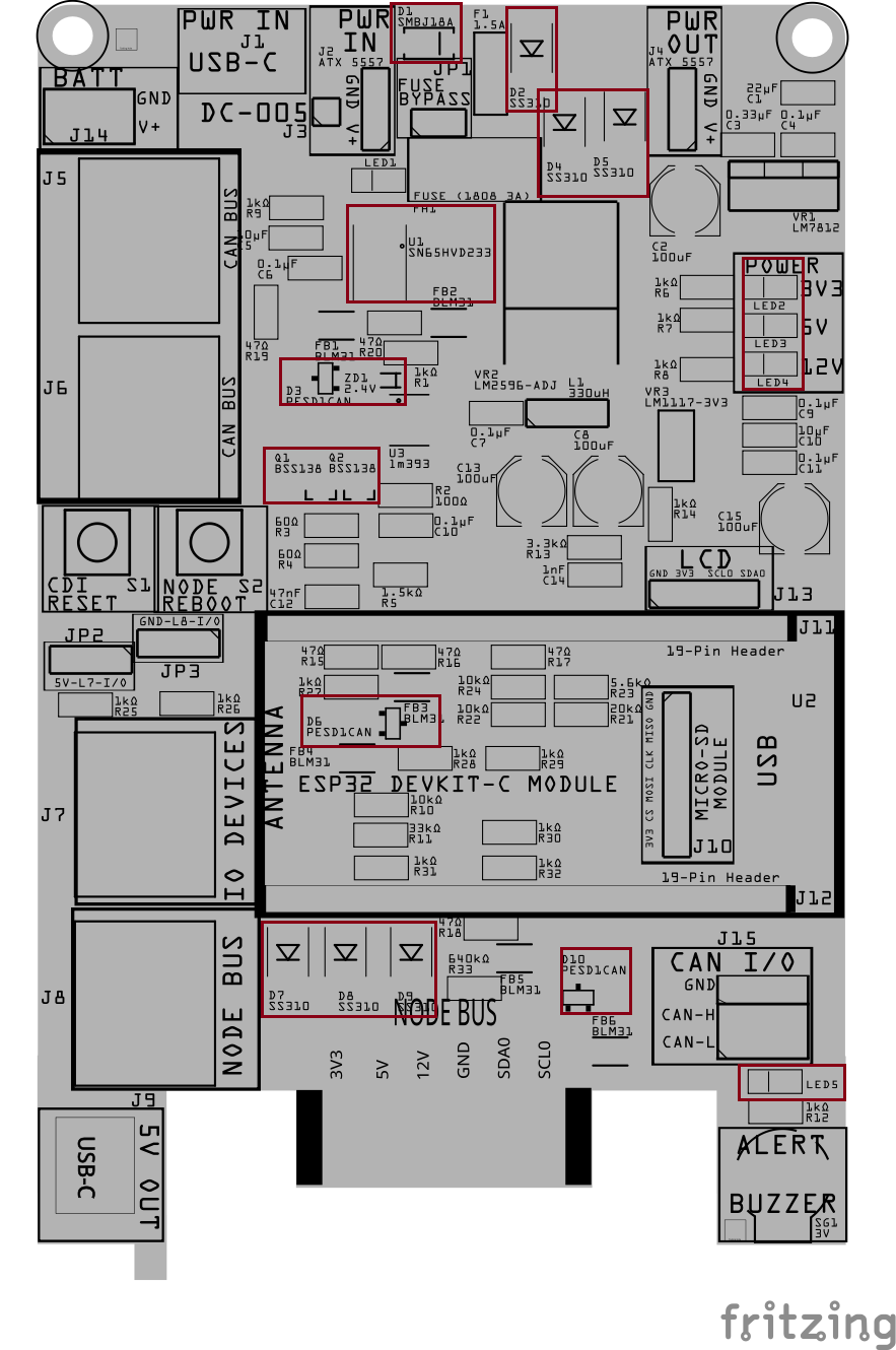
Install the small surface-mount components that must be placed in a specific direction.
This includes:
- Diodes (Dx)
- Zener diodes (ZDx)
- LEDs (LEDx)
- Transistors (Qx)
- PESD1CAN ESD protection diodes (Dx)
- Small ICs (Ux), such as logic or interface chips
These parts must be oriented correctly:
- Match the stripe, dot, or notch on the part
- Align it with the marking on the PCB silkscreen
- For LEDs, refer to the back of the LED for the cathode markings
Take your time with this step—correct orientation here prevents problems later.
Step 7: Install Larger SMD Components
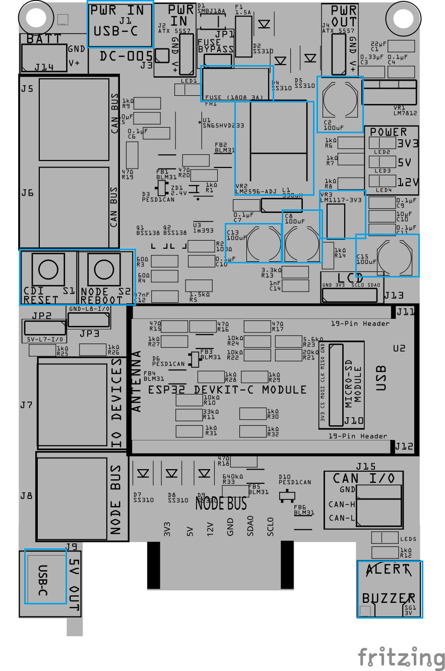
Install the larger surface-mount components that sit higher on the board and are easier to place once the small parts are done.
This includes:
- Larger polymer or electrolytic capacitors (Cx)
- SMD fuse holder (Fx)
- SMD connectors (Jx), such as USB-C
- Tactile switches (SWx)
- SMD voltage regulators (VRx)
- Buzzer
For polarized parts:
- Match the polarity marking on the component
- Align it with the PCB silkscreen
For connectors and switches:
- Ensure the part sits flat and square on the PCB before reflow
PTH Assembly
Step 8: Install Through-Hole Components
Install the through-hole components while the board is still flat and before reflow.
This includes:
- Fuse (Fx)
- Connectors (Jx), if used
- Inductor (Lx)
- Switches (SWx)
- Female Headers (Jx)
- Male Pins (JPx)
- Voltage regulators (VRx)
To keep these parts from moving during reflow:
- Apply a small amount of solder paste to at least two holes f
- or each through-hole component
- Insert the component fully so it sits flush against the PCB
- The solder paste will hold the part in place during the reflow step
Do not solder the leads yet—final soldering will be done after reflow.
Note: Applying paste to two holes is enough to hold the part during reflow.
Solder PCB
Step 9: Reflow Solder
- Place the board with standoffs into the reflow oven (place tin foil on the wire rack to support the 4x standoffs).
- Reflow the board until all solder paste has flowed and joints appear smooth and shiny.
- Remove the board and allow it to cool naturally. Do not disturb components while the solder is cooling.
- Inspect all solder joints under magnification:
- No solder bridges
- No tombstoned or shifted parts
- Clean, even fillets on pads and leads
Step 10: Solder PTH (Plated Through-Hole Components)
Most PTH components were tacked in place during reflow to hold alignment. This step completes the mechanical and electrical soldering.
- Verify Alignment
- Confirm each PTH component is fully seated onto the PCB.○
- If needed, reheat a single pin and adjust before proceeding.
- Complete Soldering
- Fully solder all pins for each PTH component.
- Ensure solder flows through the hole and wets both the pad and lead.
- Trim and Inspect
- Trim excess lead length.
- Inspect for incomplete fill, lifted pads, or accidental bridges.
- Clean (Optional)
- Remove flux residue if needed to improve visibility for upcoming testing.