See the How to Use Assembly Guides for detailed instructions.
Power-CAN Card Assembly Guide
Table of contents
Table of contents
Introduction
See the How to Use Assembly Guides for detailed instructions.
The Power-CAN Card is a critical component of the LCC Fusion Project, delivering both robust power distribution and reliable CAN (Controller Area Network) connectivity throughout the system. Designed to ensure efficient power management and seamless communication between nodes, the Power-CAN Card is primarily used with the Quad-Node Card to supply regulated power and enable CAN messaging. Each Node Bus Hub can support up to two Power-CAN Cards, effectively doubling the available power capacity for larger or more demanding configurations.
While the Power-CAN Card is essential for applications involving the Quad-Node Card, it is optional with the Node Card—which already integrates power and CAN functionality—though its inclusion enhances power distribution and provides valuable redundancy when needed. The card supports a variety of power input options to accommodate different configurations, offering flexibility in how power is delivered to the Node Card and other connected elements. For detailed power configurations and recommended setups, please refer to the Power-CAN Card Planning Guide.
Power Monitoring
In addition to its primary roles, the Power-CAN Card is engineered to continuously monitor critical parameters of your power system. It tracks the input voltage, current, and overall power consumption, as well as the output levels of 12 VDC, 5V, and 3.3 VDC. This integrated monitoring functionality not only helps ensure efficient performance but also enables early detection of potential issues, thereby safeguarding system reliability. For enhanced usability, an optional OLED display can be mounted on a 4-pin header to provide real-time visual feedback. This display can be customized to show essential data at preset intervals, making it easier for users to assess system performance at a glance.
flowchart LR;
can["CAN Network"];
n["Quad-Node Card"];
c["Power-CAN Card (2x)"];
p["Power Supply"];
hub["Node Bus Nub"];
ioc["LCC Fusion Cards"];
oled["Display"];
subgraph layout ["Train Layout"];
direction LR;
can <--> c;
p --> c;
c <--> |"CAN Comm, <br/> Power(3V3,5 VDC,12 VDC)"| hub;
hub -->  |"CAN Comm, <br/> Power (5 VDC)"| n;
hub --> |"Power <br/> (3V3,5 VDC,12 VDC)"| ioc;
hub --> |"Voltage Levels"| oled;
end;
classDef lSalmonStyle fill:#FFA07A,stroke:#333,stroke-width:2px,font-size:24px;
class c lSalmonStyle;
classDef lightGrayStyle fill:#d3d3d3,stroke:#333,stroke-width:2px,font-size:24px;
class layout lightGrayStyle;
Assembly-Configuration Options
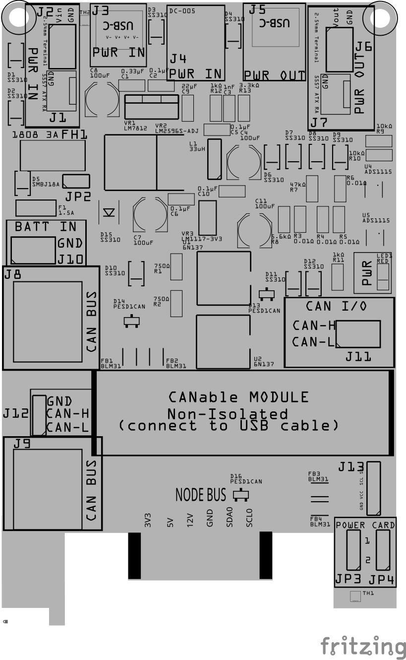
The Power-CAN Card supports multiple assembly configurations to fit various use cases.
![]()
<img src="/LccFusionProject/assets/images/pcbs/Power_CAN_Card/Power_CAN_Card_Options_pcb.png" style="zoom:75%;" />
The PCB diagram shown above highlights different components based on their associated configuration. Each color-coded component corresponds to a specific configuration, which is further detailed in the table below.
To use this reference effectively:
- Match the Colors: Each assembly option in the table has a matching color in the PCB diagram. This helps identify which components are needed for a specific configuration.
- Locate Components Quickly: The highlighted component designators (e.g., D5, J1, JP2) on the PCB indicate where each part is placed.
- Identify Required vs. Optional Parts: The table differentiates between required components (essential for functionality) and optional components (enhancements or variations).
- Cross-Reference for Clarity: If you’re unsure about a part’s placement, use the designator labels on the PCB along with the descriptions in the table.
This approach ensures a clear, visual guide for assembling the Power-CAN Card based on your specific needs.
![]()
| Configuration | Required/Optional | Description | Required Components | Optional Components |
|---|---|---|---|---|
| Power-Input | Required | Provides power input connectors with high-voltage transient protection and input filtering. | • TVS Protection: diode D5 • Reverse‑polarity Protection: diode D15 • Overcurrent Protection: Slow‑burn fuse F1 • 3A Fuse Holder: FH1 with 3A fuse AND/OR bypass selectable via header JP2 |
• Wired Power In Connector with Reverse Protection (either J1/D2 or J2/D1) • USB‑C Power In Socket with Reverse Current Protection (J3/D3) • DC‑005 Power In Connector with Reverse Current Protection (J4/D4) |
| 3.3 VDC Output | Required | Supplies regulated 3.3 VDC to the Node Bus. | • 3.3 VDC Regulated Output: Voltage regulator VR3 with associated capacitor/resistor network (R4) • Reverse Current Protection: Diode D11 |
None |
| 5 VDC Output | Required | Supplies regulated 5V to the Node Bus with proper filtering and protection. | • 5V Regulated Output: Buck regulator VR2 accompanied by input filter capacitors C1 (680 µF). C2 (100 uF), C3 (0.1 µF) and C4 (0.33 µF), inductor L1, and fuse F1 • Reverse/Output Protection: Diode D12 • Shunt resistor R5 |
None |
| 12 VDC Output | Optional | Provides regulated 12 VDC (or higher) for powering external devices and the LCC Fusion Node Bus Hub. | • 12 VDC Regulated Output: Voltage regulator VR1 • Reverse/Output Protection: Schottky diodes D6, D7, D8, D9 • Power Selection 3-Pin Header JP1 with Jumper cap SH1 (set to INPUT when NOT using the 12 VDC regulator) • Shunt resistor R6 |
• 12 VDC Output Connectors: J5, J6, or J7 (for 12 VDC @ 3A output) |
| CAT-Wired CAN BUS Option | Optional | Enables wired CAN Bus connectivity over CAT network cable, supporting data exchange with other LCC Fusion Nodes. | • Reverse Polarity Protection: Diode D10 (protects input power from CAN Bus connectors) • CAN Bus Noise Suppression: Ferrite beads FB1 and FB2 |
• CAN Bus Connections: RJ45 connectors J8 and/or J9 • ESD Protection: Diode D14 |
| 2-Wired CAN BUS Option | Optional | Enables wired CAN Bus connectivity over 2-wire, supporting data exchange with other LCC Fusion Nodes or to a computer via a remotely wired CANable module. | • CANable Module Connector: Header J11 • Isolation: High‑speed optocouplers U1 and U2 • Current Limiting for Optocouplers: Resistors R1 and R2 (750 Ω) • CAN Bus Noise Suppression: Ferrite beads FB1 and FB2 |
• ESD Protection: Diode D13 |
| CANable Module Option | Optional | Supports connection of a 2/3-wired CANable module for interfacing with a computer. | • CANable Module Connector: Header J12 • Isolation: High‑speed optocouplers U1 and U2 • Current Limiting for Optocouplers: Resistors R1 and R2 (750 Ω) • CAN Bus Noise Suppression: Ferrite beads FB1 and FB2 |
• ESD Protection: Diode D13 |
| Indicators and Controls Support Option | Optional | Provides visual power indicators and firmware control interfaces. | • Power Indicator: LED LED1 with current‑limiting resistor R3 | None |
| Battery Backup Support Option | Optional | Enables battery backup for increased system availability. | • Battery Connector: J10 | None |
| Power Monitoring | Optional | Monitors voltage, voltage drop, and current for input and output power using onboard sensors. | • Monitoring Interface: Connector J13 and selection jumpers JP3/JP4 (to assign a unique Power‑CAN Card I2C address, 0x48 - 0x4B) • I2C Noise Filtering: Ferrite Beads FB3 and FB4 • ADC for Measurement: Digital converters U3 and U4 (ADS1115) • Voltage Dividers: Resistors R7, R8, R9, R10 |
• Display: 0.96” OLED display options (PCB side‑mounted via 2x female 4‑pin headers, PCB bottom‑mounted via a 4‑pin male header, or tethered via 2x 4‑pin male headers with a 4‑wire ribbon cable) • I2C Bus Protection: Diode D16 (for ESD protection on the I2C data bus) |
Assembly and Component Placement
This section combines both the component specifications and the assembly instructions to ensure a smooth assembly process. Below is a comprehensive list of components, their placement on the PCB, and orientation details to assist you during assembly.
High-Level Steps for Assembly:
- PCB for the card can be ordered from any PCB fabricator using these Gerber Files.
- Clean PCB with alcohol to remove residue. See Cleaning_PCB for details.
- See also: Soldering Tips
- PCB Components - listing of components used for PCB assembly
- PCB Parts - listing of parts used for PCB assembly
Below is a list of the PCB components used for this card (see diagram before reference):
![]()
![]()
| Component Identifier | Count | Type | Value | Package | Purpose | Orientation |
|---|---|---|---|---|---|---|
| Capacitors | ||||||
| C1 | 1 | Capacitor-Ceramic | 0.33uF | 1206, X7R | Used by 12 VDC voltage regulator for input filtering (Required when using 12 VDC voltage regulator (VR1)) | None |
| C2 | 1 | Capacitor-Ceramic | 0.1uF | 1206, X7R | Used by 12 VDC voltage regulator for input filtering (Required when using 12 VDC voltage regulator (Q1)) | None |
| C3 | 1 | Capacitor-Ceramic | 1nF | 1206, X7R | Shunts LM2596S-ADJ output high freq spikes | None |
| C4, C7, C8, C11 | 4 | Capacitor-Polymer Solid | 100µF | 6.3x5.8mm, SMD | Used by 3V3, 5 VDC, 12 VDC voltage regulators for input/output filtering | Anode positioned toward PCB top edge |
| C5, C10 | 1 | Capacitor-Ceramic | 0.1uF | 1206, X7R | Smooths the LM1117-3V3 and LM2596S-ADJ output voltages | None |
| C6 | 1 | Capacitor-Ceramic | 0.1uF | 1206, X7R | Used by 5V voltage regulator for input filtering | None |
| C9 | 1 | Capacitor-Ceramic | 22uF | 1206, X7R | Used by 5V voltage regulator for output filtering | None |
| Diodes | ||||||
| D1 - D4 | 4 | Diode-Schottky | SS310 | SMD | Circuit protection (Required when providing power input (J1, J2, J3, or J4)) | Cathode end has a white line and positioned towards PCB top edge |
| D5 | 1 | TVS Diode | SMBJ18A | SMB SMD | Protects from high-voltage transients (>29 VDC) | Cathode end has a white line and positioned towards PCB top edge |
| D6 | 1 | Diode-Schottky | SS310 | SMD | Required by LM2596 | Cathode end has a white line and positioned towards PCB bottom edge |
| D7, D11, D12 | 3 | Diode-Schottky | SS310 | SMD | Circuit protection for reverse voltage from the LCC Fusion Node Bus Hub | Cathode end has a white line and positioned towards PCB bottom edge |
| D8, D9 | 2 | Diode-Schottky | SS310 | SMD | Circuit protection from reverse current from the output linesc | Cathode end has a white line and positioned towards PCB bottom edge |
| D10 | 1 | Diode-Schottky | SS310 | SMD | Circuit protection (Required when providing input power from CAN (J8 or J9)) | Cathode end has a white line and positioned towards PCB top edge |
| D13, D14 | 2 | ESD Diode | PESD1CAN | SOT-23 SMD | CAN Bus data electrostatic discharge (ESD) protection | Fits only one way |
| D15 | 1 | Diode-Schottky | SS310 | SMA SMD | Protects against reverse polarity from ACC BUS. | Cathode end has a white line and positioned towards PCB bottom edge |
| D16 | 1 | ESD Diode | PESD1CAN | SOT-23 SMD | I2C data bus electrostatic discharge (ESD) protection | Fits only one way |
| Fuses & Protection | ||||||
| F1 | 1 | Fuse-PTC Polymer | JK30, 1.5A, 16 VDC (or more) | 5.1mm pitch, PTH | Protects from sustained overcurrent conditions | None |
| FH1 | 1 | Fuse Holder | 1808 (/w 3A) | SMD | Protects from sustained overcurrent conditions | None |
| Filters & Noise Suppression | ||||||
| FB1, FB2 | 2 | Ferrite Bead | BLM31PG121SN1L | 1206 SMD | CAN Network Bus Data Line Noise Suppression Ferrite Bead | None |
| FB3, FB4 | 2 | Ferrite Bead | BLM31PG121SN1L | 1206 SMD | I2C Data Line Noise Suppression Ferrite Bead | None |
| Connectors | ||||||
| J1 | 1 | Connector | 5557 ATX RA | PTH | Power input connector to power the LCC Fusion Node Card when power is not being supplied via the CAN Network Bus cable | GND pin is marked on board with square pad |
| J2 | 1 | Connector | Spring/Screw | 2.54mm pitch, PTH | Power input connector to power the LCC Fusion Node Card when power is not being supplied via the CAN Network Bus cable | Position connections outward |
| J3 | 1 | Connector | USB-C Socket | 4-Pin SMD | Power input connector to power the LCC Fusion Node Card when power is not being supplied via the CAN Network Bus cable | Fits only one way |
| J4 | 1 | Connector | Power Jack | DC-005, PTH | Power input connector to power the LCC Fusion Node Card when power is not being supplied via the CAN Network Bus cable | Fits only one way |
| J5 | 1 | Connector | USB-C Socket | 4-Pin SMD | Power output connector used to power other 12 VDC+ devices | Fits only one way |
| J6 | 2 | Connector | Spring/Screw | 2.54mm pitch, PTH | Power output connector used to power other 12 VDC+ devices | Position connections outward |
| J7 | 1 | Connector | 5557 ATX RA | PTH | Power output connector used to power other 12 VDC+ devices | GND pin is marked on board with square pad |
| J8, J9 | 2 | RJ45 Socket | 8P8C | PTH | Network cable connector for Power and CAN. See notes above for required cable wiring | Fits only one way |
| J10 | 1 | JST XH Socket Spring/Screw |
2P, 2.54mm Connector |
PTH | Battery connection from Battery Card | Position connections outward |
| J11 | 1 | Spring/Screw | 2.54mm pitch | PTH | CAN Network connection for use with CANable Module (without isolation), or direct wiring | Position connections outward |
| J121 | 1 | Male header | 3-Pin, right angle, 2.54mm pitch | PTH | CAN Network connection for use with CANable Module | None |
| J13 | 1 | Male Header | 4-Pin, 2.54mm | PTH | Used to connect 0.96” OLED Display | None |
| Selectors | ||||||
| JP1 | 1 | Male Header | 3-Pin, 2.54mm | PTH | Used to select whether to regulate input voltage to 12 VDC+ or bypass to use power supplied voltage | None |
| JP2 | 1 | Male Header | 2-Pin, 2.54mm | PTH | Used to bypass the inline 3A fast blow fuse (FH1) | None |
| JP3, JP4 | 2 | Male Header | 2-Pin, 2.54mm | PTH | Used to select the Power-CAN Card number (1 or 2) within the LCC Node Cluster (determine unique I2C communications) of the ADS1115 IC’s | None |
| SH1-SH4 | 4 | Jumper Cap | 2.54mm pitch | N/A | Used with JP1-JP4 | None |
| Indicators | ||||||
| LED1 | 1 | LED | Red | 1206 SMD | Power indicator | Reference back of LED, position cathode towards PCB left edge |
| Inductors & Resistors | ||||||
| L1 | 1 | Inductor | 33uH | PTH | Used for 5V voltage regulation | None |
| R1, R2 | 2 | Resistor1 | 1206 SMD | Required when using a CAN Adapter. Limits current to optocoupler (LEDs). Use 750Ω to limit current to 5mA | None | |
| R3, R4, R5, R6 | 4 | Shunt Resistor | 0.01Ω , 0.25W | 1206 SMD | Used in differential voltage measurement. | None |
| R7 | 1 | Resistor | 47kΩ | 1206 SMD | Voltage Divider for 12 VDC input (R1/R2). | None |
| R8 | 1 | Resistor | 5.6kΩ | 1206 SMD | Voltage Divider for 12 VDC input (R1/R2). | Non |
| R9 | 1 | Resistor | 10kΩ | 1206 SMD | Voltage Divider for 40 VDC input (R1 – High Side). | None |
| R10 | 1 | Resistor | 1kΩ | 1206 SMD | Voltage Divider for 40 VDC input (R2 – Low Side). | None |
| R11 | 1 | Resistor | 1k Ω | 1206 SMD | Current limiting to Power LED | None |
| R12 | 1 | Resistor | 1k Ω | 1206 SMD | Regulator voltage divider (R1) | None |
| R13 | 1 | Resistor | 3.3k Ω | 1206 SMD | Regulator voltage divider (R2) damping lower freq. | None |
| R14, R15 | 2 | Resistor | 10k Ω | 1206 SMD | Voltage Dividers for 3V3. | None |
| ICs | ||||||
| U1, U2 | 2 | Optocoupler | 6N137 | DIP8, PTH | Required when using a CAN Adapter to provide Windows protection from the CAN network | Position IC’s indent towards PCB right edge |
| U3, U4 | 2 | Analog to Digital Converter | ADS1115 | MSOP-10 SMD | Used to convert the analog voltage reading into digital and transmitting via I2C to Power Node | Position IC’s corner dimple (pin 1) towards PCB top/right edges |
| Voltage Regulators | ||||||
| VR1 | 1 | Voltage Regulator | L7812CV | TO-220, PTH | 12 VDC voltage regulator for LCC Fusion Node Bus Hub | Position Heat sink towards PCB top edge |
| VR2 | 1 | Voltage Regulator | LM2596-ADJ | TO-263 KTT, SMD | 5V voltage regulator (buck) for ESP32 Development Board and Node Bus Hub | Fits only one way |
| VR3 | 1 | Voltage Regulator | LM1117-3V3 | SMD | 3V3 voltage regulator for Node Bus Hub | Fits only one way |
- When connecting a CANable Adapter with isolation, avoid connecting to the adapter’s GND pin to maintain isolation.
Tools Required
Safety Precautions
- See Safety Precautions.
Testing and Verification
Before integrating your Power‑CAN Card into your system, it is essential to confirm that the assembly is correct and that all electrical connections are sound. Follow these steps to ensure the board is ready for operation.
Visual Inspection
- Initial Check: Examine the board thoroughly for any obvious issues, such as: • Missing components • Solder bridges between pads • Misaligned or loosely seated components
- Solder Joint Inspection: Using a magnifying glass or microscope, inspect each solder joint for: • Cold or dull solder joints • Insufficient or excessive solder • Unintended shorts between adjacent pads
- Component Orientation: Verify that all polarized components (diodes, electrolytic capacitors, voltage regulators, etc.) and ICs are oriented correctly according to the PCB silkscreen and schematic. Double-check critical components such as diodes (look for the marked cathode) and voltage regulators (ensure proper pin‑1 orientation).
Connectivity Testing
- Continuity Check: Use a multimeter set to continuity mode to verify that: • There are no shorts between power rails and ground • All critical connections (traces, solder joints, and component leads) are continuous This helps ensure that the board has been assembled correctly and that no unintended open circuits or shorts are present.
Power-Up Tests
Important: Perform these tests before connecting the Power‑CAN Card to a Power Node.
- Input Power Verification:
• Supply at least 12 VDC to each of the designated input power connectors (J1, J2, J3, and/or J6) that you plan to use.
• Set the OUTPUT POWER selector (JP1) to
12 VDCif using the 12 VDC regulation mode. - Voltage Measurement: Using a reliable multimeter: • Verify the 3.3 VDC and 5V outputs at the PRIMARY NODE connector (J7). • If regulating for 12 VDC, confirm that the PRIMARY NODE connector (J7) outputs a stable 12 VDC. • Check any dedicated 12 VDC output connectors (J4 and/or J5) to ensure they are supplying the proper voltage.
- Thermal Check: During initial power-up, monitor the board for any components that become excessively hot. Overheating may indicate assembly errors, shorts, or incorrect component placement and should be corrected immediately.
Functional Testing
- System Integration: Connect the Power‑CAN Card to the LCC Fusion Node Card and power up the combined system.
- Network Connectivity: Use the LCC Configuration Tool to verify that the Node successfully connects to the LCC Node network. This confirms that the communication and power interfaces are functioning correctly.
- Power Monitoring Validation: • Set the Power Card selector (via JP3/JP4) to assign a unique card number (e.g., card 1 or 2). • Install the 0.96” OLED display (connected via J13) according to your chosen mounting option. • Confirm that the OLED display accurately shows voltage, current, and power readings for the 3.3 VDC, 5V, and 12 VDC rails.
Additional Recommendations
- Documentation: Record all test results and note any modifications or corrections made during the assembly process.
- Safety Precautions: Use a current-limited power supply during initial testing to protect the board in case of shorts or assembly errors.
- Iterative Testing: If any issues are detected during any stage of testing, resolve them before proceeding to final integration.
Troubleshooting
- Reference the provided PCB diagrams while testing connections.
- Verify connections between pins using ohm meter.
- When regulated power is not detected, check for input voltage at each of the regulators.
- Test for a ground connection supply GND, output GND, and each of the IC GND pins.
Appendences
PCB Specifications
Specifications for the Power-CAN Card include:
When using multiple Node Cards or Quad-Node Cards, consider using ATX, terminal, or DC-005 barrel connector to provide 5V @ 3A to the Node Bus Hub.

| Characteristic | Value |
|---|---|
| Nodes: Max number of Nodes (assuming 100 mA avg per Node ESP32) | 30 |
| Power-CAN Cards: Max number of Power-CAN Cards per Node Cluster5 | 2 |
| Input: Max supply voltage (limit of 25 VDC capacitor C5) | 25 VDC |
| Input: Max supply current via CAN Bus network cable (limited by network cable’s 2 combined power wires) | 1.2A |
| Input: Max supply current via ATX 5557, Spring/Screw Terminal Connector, or DC-005 connector | 3A |
| Input: Max supply current USB-C connector (without 12 VDC regulator, connector limit) | 2A |
| Output: Max 3V3 output current (LM1117-3V3 regulator limitation) | 800 mA |
| Output: Max supply current to output ATX 5557 or Spring/Screw Terminal connectors | 3A |
| Output: Max 5V output current to Node Bus Hub1,3 | 3A |
| Output: Max 12 VDC2, 3 to the Node Bus Hub | 1.5A |
| Output: Max output current via USB-C | 2A |
| Output: Max output voltage to ATX 5557 or Spring/Screw Terminal Connector | Input Voltage minus ~0.4 - 1.7 VDC4 |
- Voltage Regulator (LM2596-5) has a 5A limit, but output is limit is reduced to 3A by traces (54 mil), vias (0.6mm hole), diodes (SS310), and 3A polyfuse (resettable).
- Limit of 1.5A by 12 VDC voltage regulator (L7812CV)
- Voltage drop of 0.5 VDC is caused by reverse voltage protection (SS310 diode in series)
- Voltage drop is caused by reverse voltage protection (two SS310 diodes in series), drop increase with current
- Limit of Node Bus Hub (3A) within the Node Cluster (one or more Node Bus Hubs connected together via pin headers)
How It Works
The Power-CAN Card supports both power distribution and CAN network connectivity across LCC Fusion devices. It connects to the Node Bus Hub and enables stable power and reliable communication between multiple Node Cards and I/O modules. Key protections against network fluctuations and reverse voltage are built in; see Protection for more.
CAN Network
The Power-CAN Card includes galvanic isolation for CAN lines using 6N137 high-speed optocouplers, which shield the LCC Fusion network from ground loops, voltage spikes, and potential security issues such as unauthorized data access or network snooping from external devices. Users can connect the card to the CAN network via network cables, direct wiring, or a CANable adapter.
Correct termination of the CAN network is essential for reliable data transmission. To meet this, the Node Card and Quad-Node Card (cards an MCU connected to the CAN bus) support auto-termination by detecting low voltage and applying a 120Ω resistor as needed.
Power Supplied to Node Bus Hub
The Power-CAN Card provides regulated power to the Node Bus Hub, with various connection and regulation options (see Protection and Connections for more details):
- The OUTPUT POWER selector allows users to set the power output to 12 VDC via a linear regulator or to bypass it, using the input supply voltage for >12 VDC needs.
- When set to 12 VDC, the L7812CV regulator converts the supply voltage to 12 VDC for use by both the Power-CAN Card and the Node Bus Hub.
- A LM2596-5 switching regulator provides a steady 5 VDC supply for the Node Bus Hub.
- A LM1117-3V3 linear regulator supplies 3.3 VDC to the Hub, meeting the lower voltage requirements of certain modules.
- Overcurrent protection is provided by two resettable polyfuses rated at 1.5A and 3A.
- Reverse polarity protection is included via diodes on each output line.
- Noise filtering is implemented with capacitors on both input and output lines to stabilize and clean the power signal.
This modular design also supports adding multiple Power-CAN Cards to a single Node Bus Hub to expand both power capacity and CAN connectivity, enabling flexible scaling for complex automation configurations.
Power Monitoring
In addition to its core functions, the Power-CAN Card features integrated power monitoring. An ADS1115 ADC is used to continuously measure critical voltages across the system—including the input power voltage (up to 40 VDC) and the regulated outputs (12 VDC, 5V, and 3.3 VDC)—by sampling voltage drops across precision shunt resistors and voltage divider networks. These measurements are transmitted via I²C to the Node Card, which aggregates the data and relays the information back to the Power-CAN Card. Optionally, an OLED display (mounted on a 4-pin male header) on the Power-CAN Card provides real-time visual feedback of these measurements, enabling users to quickly assess power performance and detect potential issues early. This monitoring function enhances system reliability by ensuring that power distribution remains within safe operating limits.
| Voltage Rail | ADS | AIN Pin(s) | Function | Divider (R1/R2) | Notes | ADS-1115 I2C Addr (Power-CAN Card 1) | ADS-1115 I2C Addr (Power-CAN Card 2) |
|---|---|---|---|---|---|---|---|
| 40V | ADS-1 | AIN0 (V), AIN1 (shunt) | Voltage + Current | 10k / 1k | AIN0 via divider, differential (AIN0–AIN1) for current | 0x48 (GND) | 0x49 (VCC) |
| 12V | ADS-1 | AIN2 (V), AIN3 (shunt) | Voltage + Current | 47k / 5.6k | AIN2 via divider, differential (AIN2–AIN3) for current | 0x48 (GND) | 0x49 (VCC) |
| 5V | ADS-2 | AIN0 (V), AIN1 (shunt) | Voltage + Current | 10k / 10k | AIN0 via divider (recently added), differential (AIN0–AIN1) for current | 0x4A (SDA) | 0x4B (SCL) |
| 3.3V | ADS-2 | AIN2 (V), AIN3 (shunt) | Voltage + Current | None | Only current measured using AIN2–AIN3 differential | 0x4A (SDA) | 0x4B (SCL) |
Power Monitor Output
OLED Display Support
- Detection & Initialization: the firmware’s monitor scans I²C address
0x3Cfor a 128×64 SSD1306 OLED. - Display Buffering: If found, readings for the four rails (40 V, 12 V, 5 V, and 3.3 V) are rendered as four lines of text.
- I²C Address:
0x3C(standard SSD1306 default).
OLED Text Layout
40V: xx.xV xx.xV x.xA xx.xW
12V: xx.xV xx.xV x.xA xx.xW
5V : xx.xV xx.xV x.xA xx.xW
3.3V:xx.xV xx.xV x.xA xx.xW
- First column: raw voltage
- Second column: voltage after shunt drop
- Third column: current in A (one decimal)
- Fourth column: power in W (no decimal if ≥10 W)
Serial Monitoring
-
Automatic Multi-Line Output: Writes all detected rails to the Serial console.
-
Multi-Card Support: If two Power‑CAN cards are present, output is grouped by card:
=== Power-CAN Card 1 ===
40V: 38.72 VDC, 0.52 A, 20.13 W
12V: 12.03 VDC, 0.15 A, 1.80 W
=== Power-CAN Card 2 ===
5V :  5.00 VDC, 0.10 A, 0.50 W
3.3V: 3.30 VDC, 0.05 A, 0.16 W
Connections
This section provides an overview of the connections for this card.
![]()
| Component Designator | Connector Label | Connector Type | Connection Number | Function | Description |
|---|---|---|---|---|---|
| NODE BUS | Card Edge | 1-12 | Power, Communications | Connection to Node Bus Hub | |
| J1 | PWR IN1 | ATX 5557 RA | VDC+, GND | Power In | Connection from Power Supply (14-18 VDC, 0.5-3A) |
| J2 | PWR IN1 | 2P Spring/Screw Connector | VDC+, GND | Power In | Connection from Power Supply (14-18 VDC, 0.5-3A) |
| J3 | PWR IN2 | USB-C | VDC+, GND | Power In | Connection from Power Supply (14-18 VDC, 0.5-3A) |
| J4 | PWR IN2 | DC-005 | VDC+, GND | Power In | Connection from Power Supply (14-18 VDC, 0.5-3A) |
| J5 | PWR OUT | USB-C | VDC+, GND | Power Output | Connection to next Power-CAN Card, or Node Card (14-18 VDC, 0.5-3A) |
| J6 | PWR OUT | 2P Spring/Screw Connector | VDC+, GND | Power In | Connection to next Power-CAN Card, or Node Card (14-18 VDC, 0.5-3A) |
| J7 | PWR OUT | ATX 5557 RA | VDC+, GND | Power In | Connection to next Power-CAN Card, or Node Card (14-18 VDC, 0.5-3A) |
| J8, J9 | CAN BUS | RJ45 Socket | 1-8 | Power & CAN In/Out | Connection to/from other LCC Nodes |
| J10 | BATT IN | 2P JST XH, screw/spring terminal | 12 VDC, GND | Battery Card | Connection to LCC Fusion Battery Card for power backup |
| J11 | CAN I/O4 | 3-Pin Header | CAN (CAN-H, CAN-L) | CAN Network | Connection to the CAN Network. |
| J12 | CANable MODULE3, 5 | 2-Pin Header | CAN (CAN-H, CAN-L) | CANable Device/Adapter | Used to connect to a CANable device / adapter. |
| J13 | OLED Monitor | 4-Pin Header | GND, VCC, SCL, SDA | Display Monitor | Connects to the OLED display (via a 4-pin male header) to show real-time monitoring of voltage, current, and power usage (for input and outputs: 12 VDC, 5V, 3.3 VDC). |
- Recommend using train layout accessory bus which is typically >12 VDC.
- Recommend a laptop power supply with a USB-C and DC-005 connectors with typically provide 18-20 VDC and >3A (>65W) for less than $20 on Amazon.
- Provides an alternative method of connect to the CAN Network. A CANable adapters attach to computers via USB.
- This connection provides a galvanic isolation link to the CAN Network, ensuring electrical isolation between the CAN Network and LCC Fusion devices.
- This connection does NOT provide a galvanic isolation link to the CAN Network for a electrical isolation between the CAN Network and LCC Fusion devices. For protection, insure that the CANable Adapter provides the required isolation.
PCB Protection
The Power-CAN Card ensures stable voltage regulation and protection against various electrical faults for the LCC Fusion Node Card. Below is an overview of each protection component integrated into the Power-CAN Card and its role:
![]()
| Protected Component | Protection Component | Function | Specifications | Location |
|---|---|---|---|---|
| Monitoring System | ADS1115, ESP32, (Optional) OLED Display | Continuously monitors the input voltage/current/power and output levels (12 VDC, 5V, 3.3 VDC) to detect anomalies early and provide real-time data for fault detection. | Real-time monitoring with programmable thresholds; minimal voltage drop on sensor nodes; low-power operation | Integrated on the Power-CAN Card with sensor nodes connected to the power rails (input and outputs). |
| Entire Board (Relays, Devices, Voltage Regulator) | Crowbar Diode, Resettable Fuse | Crowbar Protection protects against reverse polarity by short-circuiting the power supply when connected backward, blowing the fuse to protect the circuit | Diode becomes forward-biased if reverse polarity occurs | Across the power supply input (ACC VDC+ to ACC GND) C VDC+ to ACC GND) |
| Entire Power-CAN Card | Fast Blow Fuse | Protects from current overflow | Hold Current: 3A | In series with the incoming Vcc line |
| Entire Power-CAN Card | Polyfuses | Protects from sustained overcurrent conditions by increasing resistance when the 3V3 or 5V current exceeds 1.5A. Resets once the fault condition is cleared. | Hold Current: 1.5A | In series with the 5V, 3V3 output lines |
| Entire Power-CAN Card | TVS Diode SMBJ18A | Protects from high-voltage transients by clamping voltage spikes, preventing them from reaching sensitive components. | Stand-off Voltage: 18 VDC Clamping Voltage: 29.2 VDC |
Across the incoming Vcc and GND lines |
| Input/Output Connectors | SS310 Diodes | Protect against reverse voltage by blocking current flow in the wrong direction. | Reverse Voltage: 100 VDC Forward Current: 3A |
In series with each input/output power connector |
| CAN Bus | Galvanic Isolation | Isolates CAN network from local circuitry, preventing ground loops and noise transfer. | High Speed Optocouplers (6N137) | In series between CAN transceiver and CAN bus lines |
| CAN Bus | PESD1CAN Diodes | Protect against ESD (Electrostatic Discharge) from the CAN network lines | Reverse Stand-off Voltage (Vr): 24 VDC Clamping Voltage (Vc): 40 VDC |
Across each I2C (CAN-H, CAN-L) input line and GND |
| CAN Bus | BLM31PG121SN1L Ferrite Beads | CAN Network Bus Data Line Noise Suppression Ferrite Bead | In series with the CAN network lines (CAN-H, CAN-L) | |
| LM2596-5 Regulator | Input Capacitor | Filters out high-frequency noise and transient voltage spikes from the input power supply, ensuring stable voltage regulation. | Value: 100 uF electrolytic | Across the input (Vcc) and GND |
| LM2596-5 Regulator | Output Capacitor | Filters out high-frequency noise and transient voltage spikes from the output, ensuring stable 5V regulation. | Value: 100 µF electrolytic | Across the output (5 VDC) and GND |
| L7812CV Regulator | Input Capacitor | Filters out high-frequency noise and transient voltage spikes from the input power supply, ensuring stable voltage regulation. | Value: 0.33 µF ceramic | Across the input (Vcc) and GND |
| L7812CV Regulator | Output Capacitor | Filters out high-frequency noise and transient voltage spikes from the output, ensuring stable 12 VDC regulation. | Value: 0.1 µF ceramic | Across the output (12 VDC) and GND |
| Ground Bus | 48mil Ground Bus | Provides a low-resistance path for all protection components, ensuring effective grounding and noise suppression. | Width: 48 mil | Used by all protection components |
Summary
These protection components work together to safeguard the Power-CAN Card from various electrical faults. The polyfuse provides overcurrent protection, the TVS diode clamps high-voltage spikes, and the SS310 diodes protect against reverse voltage. Decoupling capacitors filter out noi/se and transient voltage spikes, ensuring stable voltage regulation. The Power-CAN Card currently has capacitors installed for the LM2596-5 and L7812CV regulators, which help filter the input to the LM1117-3.3 VDC regulator. It is still recommended to install the 2x 10µF capacitors for the LM1117-3.3 VDC regulator to ensure optimal performance. Together, these components ensure the Power-CAN Card operates reliably, providing stable 12 VDC, 5V, and 3.3 VDC outputs to the LCC Fusion Node Card.