PWM Card - Step-By-Step Assembly Guide
[TOC]
Table of contents
Table of contents
Before You Begin
Step 1. Review Configuration Options
Before soldering, determine which options you are building:
- Power input method(s)
- CAN bus connection type
- Node Bus Hub connection (local vs remote)
- I/O device support
- Indicators, buzzer, battery backup, SD card, display
Refer to the Assembly Configuration Options in the PWM Card documentation.
See PCB Soldering for soldering details.
Step 2. Gather Tools and Materials
See Tools and Materials for detailed instructions.
Step 3. Prepare the PCB
- Inspect the PCB for damage or contamination.
- Clean both sides with isopropyl alcohol.
SMD Assembly
Do not install through-hole components, the ESP32 module, or tall connectors at this stage.
Step 4: Apply Solder Paste
See Applying Solder Paste for detailed instructions.
Step 5: Install Small SMD Components (No Orientation Required)
- Place the small surface-mount components that do not have a direction or polarity.
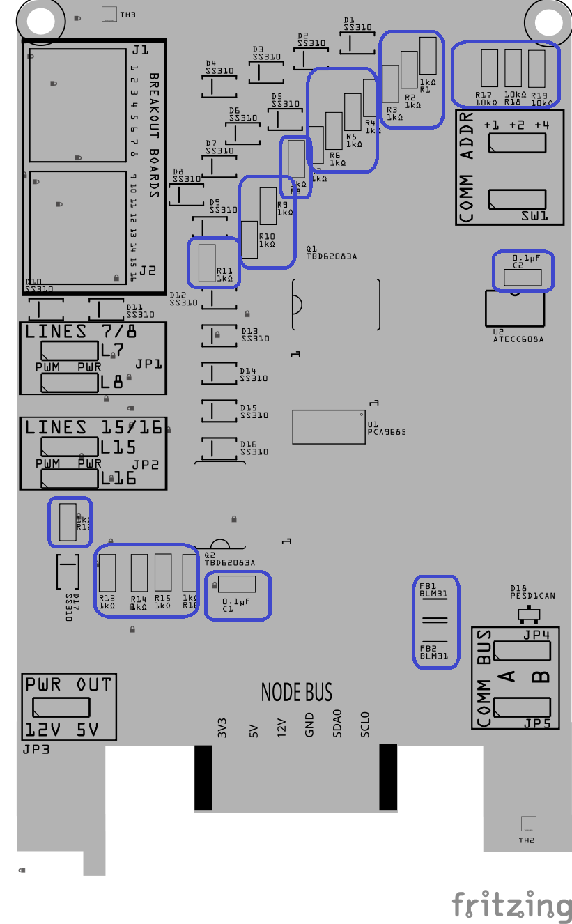
<img src=”/LccFusionProject/assets/gifs/Placing_SMD_parts.gif” alt=”Placing SMD parts (GIF)” style=”float:right; margin: 0 30px 30px 0; width: 800px;”
This includes:
- All resistors (Rx)
- Small ceramic capacitors (Cx)
- Ferrite beads (FBx)
These parts can be placed in either direction, so orientation is not critical.
Step 6: Install Small SMD Components (That Have a Direction)
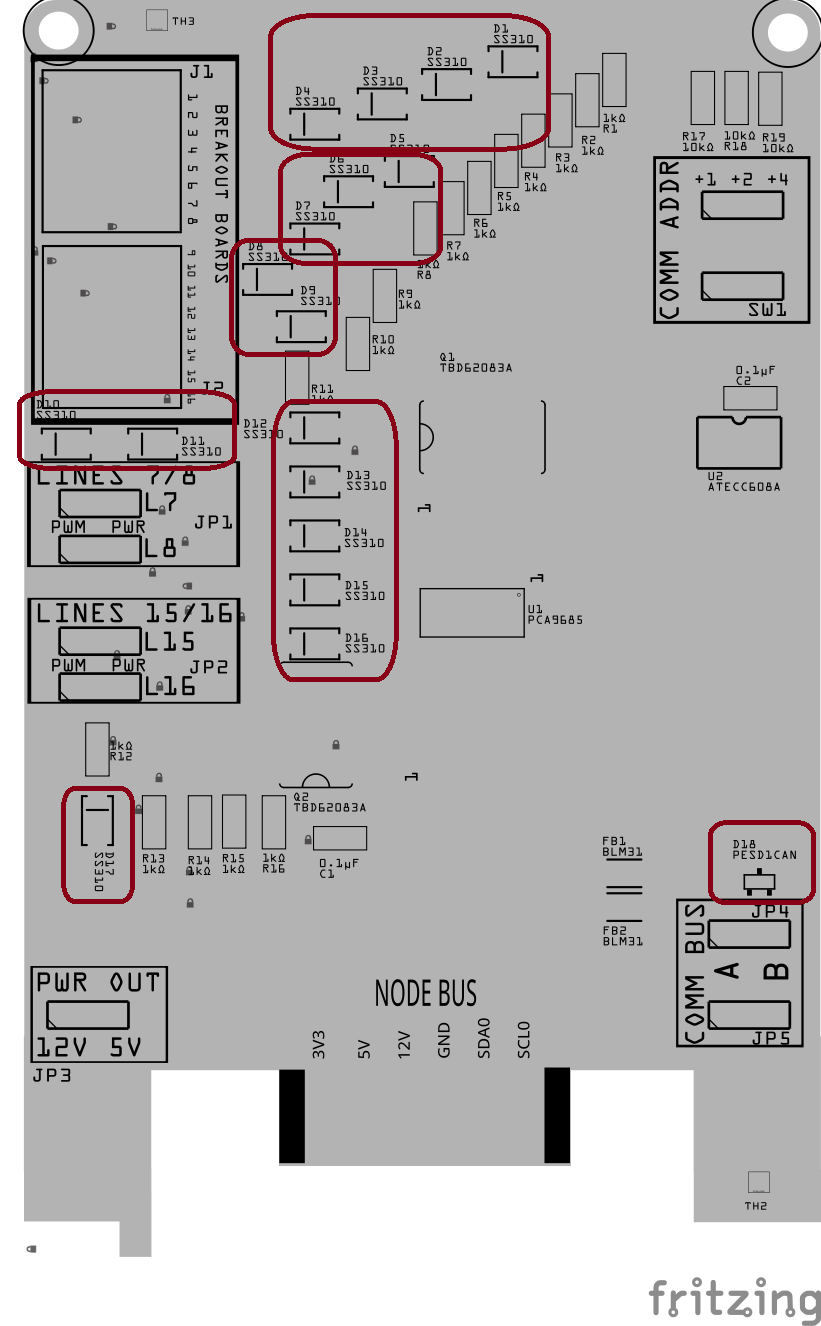
Install the small surface-mount components that must be placed in a specific direction.
This includes:
-
Diodes (Dx)
-
PESD1CAN ESD protection diodes (Dx)
-
Small ICs (Ux), such as logic or interface chips
These parts must be oriented correctly:
- Match the stripe, dot, or notch on the part
- Align it with the marking on the PCB silkscreen
Step 7: Install Larger SMD Components
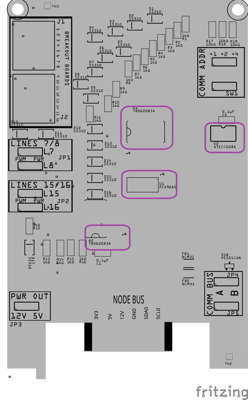
Install the larger surface-mount components that sit higher on the board and are easier to place once the small parts are done.
This includes:
-
Match the polarity marking on the component
-
Align it with the PCB silkscreen
-
Ensure the part sits flat and square on the PCB before reflow
PTH Assembly
Step 8: Install Through-Hole Components
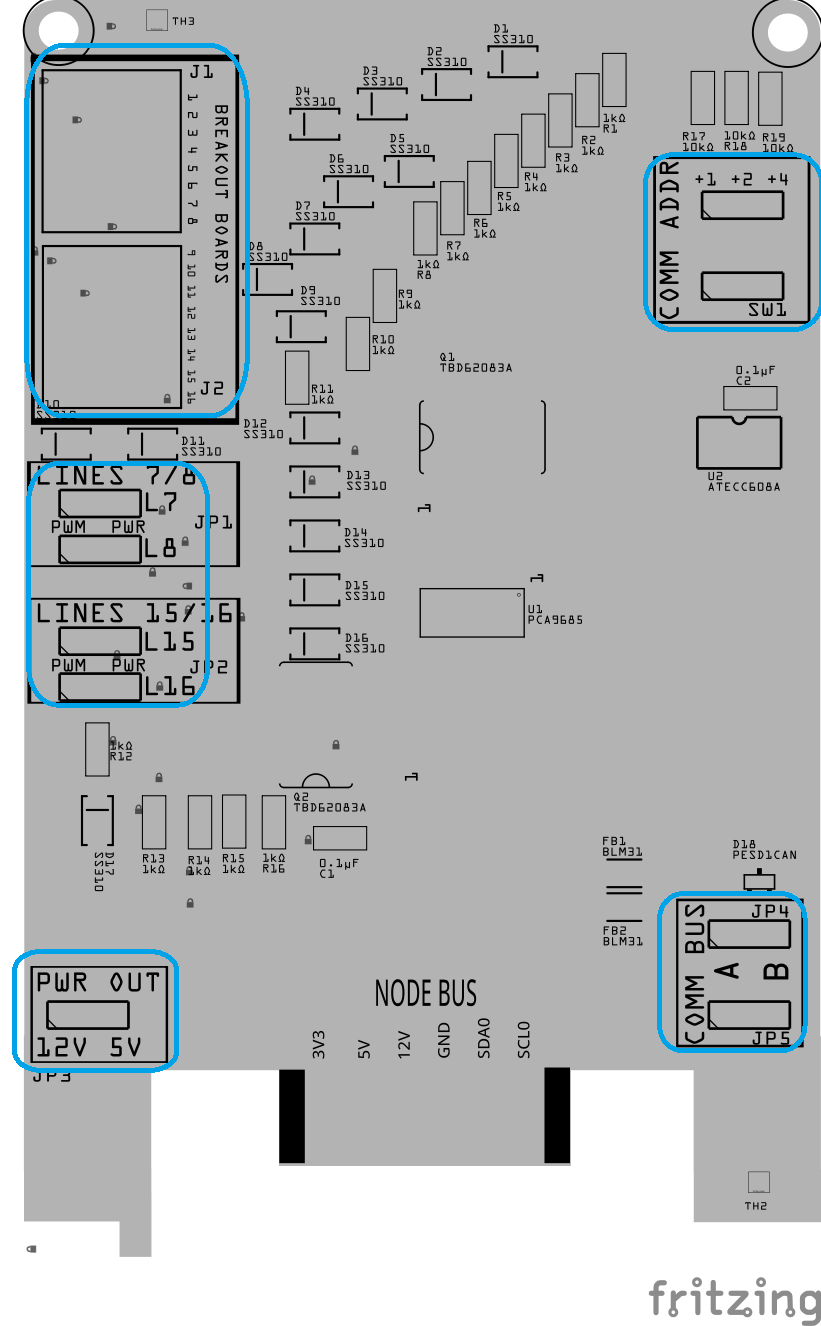
Install the through-hole components while the board is still flat and before reflow.
This includes:
-
Connectors (Jx)
-
Switches (SWx)
-
Female Headers (Jx)
-
Male Pins (JPx)
To keep these parts from moving during reflow:
- Apply a small amount of solder paste to at least two holes for each through-hole component
- Insert the PCB into the helping hands clamp, suspending the PCB
- Insert the component fully so it sits flush against the PCB
Do not solder the leads yet—final soldering will be done after reflow.
Note: Applying paste to two holes is enough to hold the part after reflow when we turn the board over to solder the pins.
Solder PCB
Step 9: Reflow Solder
- Place the board with standoffs into the reflow oven (place tin foil on the wire rack to support the 4x standoffs).
- Reflow the board until all solder paste has flowed and joints appear smooth and shiny.
- Remove the board and allow it to cool naturally. Do not disturb components while the solder is cooling.
- Inspect all solder joints under magnification:
- No solder bridges
- No tombstoned or shifted parts
- Clean, even fillets on pads and leads
Step 10: Solder PTH (Plated Through-Hole Components)
<img src=”/LccFusionProject/assets/gifs/Soldering_PTH.gif” alt=”Applying solder paste with stencil (GIF)” style=”float:right; margin: 0 30px 15px 0; width: 800px;”
Most PTH components were tacked in place during reflow to hold alignment. This step completes the mechanical and electrical soldering.
- Verify Alignment
- Confirm each PTH component is fully seated onto the PCB.○
- If needed, reheat a single pin and adjust before proceeding.
- Complete Soldering
- Fully solder all pins for each PTH component.
- Ensure solder flows through the hole and wets both the pad and lead.
- Trim and Inspect
- Trim excess lead length.
- Inspect for incomplete fill, lifted pads, or accidental bridges.
- Clean (Optional)
- Remove flux residue if needed to improve visibility for upcoming testing.