RPI-CAN Card Assembly Guide
Table of contents
Table of contents
Introduction
See the How to Use Assembly Guides for detailed instructions.
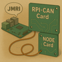
This document provides a detailed guide the assembly of the RPI-CAN Card used to configure a Raspberry PI (RPI) running the Java Model Railroad Interface (JMRI) with the Controller Area Network (CAN) interface. JMRI provides a GUI for both controlling a layout and for configuring LCC Nodes. The card provides all of the wiring connections for between an RPI, a CAN Module, and the LCC Fusion Project.
 To facilitate CAN communication with LCC Nodes, a Raspberry Pi can be configured to run JMRI and function as a CAN end-node. This integration is streamlined through the use of a specialized Raspberry Pi (RPI) CAN card that incorporates the MCP2515 module (CAN Receiver). This card, which slots directly into the LCC Fusion Node Bus Hub, simplifies connectivity by negating the need for additional wiring.
 In essence, connecting a Raspberry Pi to the LCC Node network is made straightforward with the Raspberry Pi CAN Card. The design of the card does away with the necessity of 10 separate connections:
- It eliminates the need for eight connections typically used for SPI, 3.3 VDC, and GND between the Raspberry Pi and the MCP2515.
- It also removes the requirement for two CAN wires that would normally link the MCP2515 Module to the LCC Node.
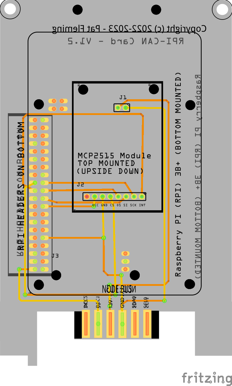
The Raspberry Pi CAN card operates as a Raspberry Pi HAT, connecting beneath the card, while the MCP2515 module is mounted upside down on the top of the PCB. Once combined, this assembly is plugged into the LCC Fusion Node Bus Hub. It provides the essential connections: the Raspberry Pi to the LCC Fusion Node Bus Hubat 5V, and the MCP2515 Module to the Node’s 3.3 VDC and CAN network. Additionally, the Raspberry Pi’s SPI is linked to the MCP2515 module through this card.
Assembly and Component Placement
This section combines both the component specifications and the assembly instructions to ensure a smooth assembly process. Below is a comprehensive list of components, their placement on the PCB, and orientation details to assist you during assembly.
High-Level Steps for Assembly:
- PCB for the card can be ordered from any PCB fabricator using these Gerber Files.
- Clean PCB with alcohol to remove residue. See Cleaning_PCB for details.
- See also: Soldering Tips
- PCB Components - listing of components used for PCB assembly
- PCB Parts - listing of parts used for PCB assembly
Below is a list of the PCB components used for this card (see diagram before reference):
![]()
![]()
| Component Identifier | Count | Type | Value/Description | Package | Purpose | Orientation |
|---|---|---|---|---|---|---|
| 1 | Raspberry PI | RPI (4B+) | N/A | Raspberry PI provides JMRI and other services for LCC Nodes. | Fits only one way | |
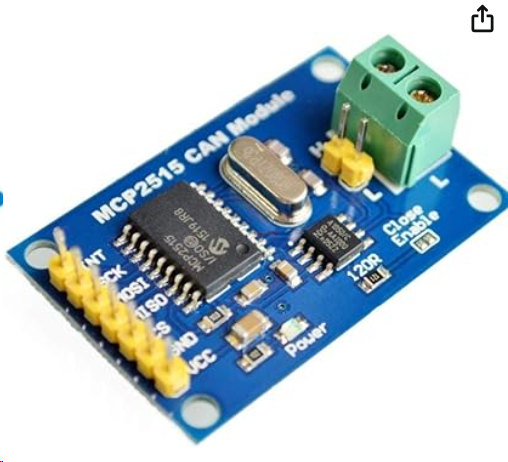
| M1 | 1 | Module | MCP2515 | CAN Module (SPI) | CAN receiver module (SPI) | Fits only one way |
| Connectors | ||||||
| J1 | 1 | Female Header | 2P Stackable Long Leg Female Header (2.54mm, straight, single row) | 2.54mm PTH | Provide CAN connections between MCP2515 Module and LCC Fusion Node Bus Hub. Headers on TOP. | None |
| J2 | 1 | Female Header | 8P Stackable Female Header (2.54mm, straight, single row) | 2.54mm PTH | Provide SPI connections between the RPI and the MCP2515 Module. Headers on TOP. | None |
| J3 | 1 | Female Header | 2x20P Female Extra Tall GPIO Stacking Headers for RPI (2.54mm, straight, double row) | 2.54mm PTH | Provide connections to the RPI (4B+) pins. Mounted under the PCB, as an RPI HAT. | None |
| SH1 | 1 | Jumper Cap | Jumper Cap (2.54mm) | 2.54mm | Used for selection setting CAN bus termination. Recommend tall caps for easy use. | None |
Tools Required
The card only requires soldering three sets of PTH female pin headers. Required tools required are:
- soldering iron
- solder
- tacky putty (hold components while soldering)
See List of recommended tools for more details on these tools.
Safety Precautions
- See Safety Precautions.
Assembly Instructions
 Here are the step-by-step instructions for assembling the card:
See also: Soldering Tips
-
Solder headers:
-
Solder each header individually.
-
Attach the 2x20P female header (J3) to the BOTTOM of the PCB. This will be used for attaching the RPI underneath the PCB using its male pins later.
-
 Solder the 2p stackable long legged header (J1) to the TOP of the PCB (long legs down thru the 2 holes). The 2 long legs provide a connection in the MCP2515 Module’s 2P male header connector (CAN-H and CAN-L communications).
 -
Solder the 8p header (J2) to the TOP of the PCB (legs down thru the 8 holes). This header provides a connection to the MCP2515 Modules power and SPI communications connector.
These will be used for connecting the MCP2515 board in an upside-down position using its male pins.
Utilize tacky putty to secure each header during the soldering process.
-
 Ensure each header is aligned straight and fits snugly against the PCB.
Tip: After soldering the first pin of a header, remove the putty, press down on the header, and reheat the soldered pin to set the header flush and straight against the PCB.
-
Complete the soldering for the rest of the pins on each header.
-
Follow this process for all headers.
-
-
 Install the MCP2515 Module on PCB
- Insert the MCP2515 Module on the PCB top, making sure both sets of male pins are inserted into PCB’s female headers correctly. Note that the CAN Termination jumper will be configured later during installation of the card.
- Attach four 10mm PCB standoffs on the PCB top to secure the MCP2515 to the board.
-
 Install the RPI
- Insert the RPI into the 2x20P headers on the PCB bottom
- Install (4) sets of 2x11mm PCB standoffs on the PCB bottom to mount the RPI, using the provided holes in the card.
Testing and Verification
The following test and verifications of the card should be performed after a through in+spection of the card’s soldering. Check all of the PTH component pins. Make sure there are no solder bridges between pins.
Visual Inspection
- Initial Check: Examine the board for any obvious issues like missing components, solder bridges, or components that are misaligned or not fully seated.
- Solder Joint Inspection: Use a magnifying glass or a microscope to inspect solder joints. Look for cold solder joints, insufficient or excessive solder, or any shorts between pads.
Power-Up Tests
- Apply Power: Without the RPI and MCP2515 Module added, check for correct voltage levels at these locations:
- Using the tabs at the base of the card, verify at the base of the card that the LCC Fusion Node Bus Hubis providing 3V3, 5V, and 12+V.
- Check for 5V at the PCB pin marked 5V.
- Check for 3V3 at the PCB pin marked 3V3.
Functional Testing
- Configure RPI for CAN communications. Refer to RPI CAN Configuration.
- Plugin in the RPI and check that it powers up correctly.
- Plugin in the MCP2515 Module and check if Linux connects to it.
- Configure a JMRI connection to verify that JMRI running on the RPI can connect to an LCC Node using wired CAN communications.
Troubleshooting
- See I2C Trouble Shooting.
Appendences
PCB Specifications
None
References
- Adding CAN to the Raspberry PI - provides information on selection of the MCP2515 board and information used in the design of RPI-CAN Card and Linux configuration.