RPi-CAN Card Installation Guide
Table of contents
Table of contents
Overview
This section outlines the steps to set up a the RPi-CAN Card with an Raspberry Pi (RPi) for integration with the LCC Fusion Node Cluster. The RPi-CAN provides all of the connections between an RPi, MCP2515 module (transceiver for CAN communications), and a Node Bus Hub. No external wiring is required.
What’s Needed
| Component | Purpose |
|---|---|
| RPi-CAN Card (assembled with Pi & MCP2515) | Interfaces between the Pi, MCP2515 module, Node Bus, and CAN Bus |
| RPI Software (OS and JMRI) | Runs JMRI for CAN communications. Use Steve Todd’s preconfigured JMRI image |
| HDMI monitor & USB keyboard/mouse | Provides a local console for initial RPi configuration and troubleshooting |
| microSD card (8 GB or larger) | Holds the preconfigured JMRI OS image |
| microSD card reader & imager | Needed to flash the JMRI image onto your card (e.g. with balenaEtcher) |
| Node Card & Power Supply | Interfaces with CAN network and cards (via Node Bus Hub) |
| Network Cable (CAT5/CAT6) | Connects the Pi (via RPi-CAN Card) to the Node Card and cards to breakout boards |
Connection Diagram
flowchart LR
  subgraph layout ["Train Layout"]
  	direction LR
  	subgraph hub["Node Bus Hub"]
      direction LR
      nodeCard[["Node Card"]]
      subgraph rpiCanCard["RPI-CAN Card"]
        rpi["RPI Module"]
        transceiver["MCP2515 Module<br>(CAN Transceiver)"]
      end
      ioCards[["I/O cards"]]
    end
    mkm["Monitor, <br>Keyboard,<br>Mouse"]
    jmri["JMRI Software<br>CDI Config Tool"]
    pwrSupply(("Power Supply"))
    breakout1["breakout boards"]
    devices1(("devices"))
  end
  mkm -.-> |"HDMI, USB"|rpi
  jmri -.- |"runs on"|rpi
  pwrSupply -.-> |"1+ A @ 40 VDC max via<br>2-wire"| nodeCard
  nodeCard <--> |"Pwr/Comm via<br>Node Bus"|ioCards
  nodeCard <--> |"Pwr/Comm via<br>Node Bus"|rpiCanCard
  ioCards <--> |"I/O via<br>Network Cable"|breakout1
  breakout1 <-.-> |"I/O via<br>2-wire"|devices1

  classDef lightBlueStyle fill:lightblue,stroke:#2c7a2c,stroke-width:2px,font-size:16px;
  classDef lightGreenStyle fill:lightgreen,stroke:#333,stroke-width:2px,font-size:20px;
  class hub lightBlueStyle
  class rpiCanCard lightGreenStyle
Connector Assignments
| Label | Pins | Function |
|---|---|---|
| J1 | 2-pin | Power connection to MCP2515 Module |
| J2 | 8-pin | Connects RPI with MCP2515 Module (power, CAN communications) |
| J3 | 4-pin | Connects RPI with RPI-CAN Card (power, CAN communications) |
Installation Steps
- Remove the MCP2515 module
- Power off the system and disconnect the RPi-CAN Card from the Node Bus Hub.
- Unscrew the two mounting screws securing the MCP2515 breakout board to the RPi-CAN Card.
- Carefully lift the MCP2515 module straight up to disengage the header pins.
- Set the CAN termination jumper
- On the underside of the MCP2515 board, locate the pads or pins labeled “TERM” or “120 Ω” between CAN_H and CAN_L.
- Place the provided 120 Ω jumper cap across those pads to enable termination.
- If this node sits in the middle of your CAN network, leave the jumper off instead.
- Reinstall the MCP2515 module
- Align the module’s header pins with the socket on the RPi-CAN Card.
- Gently press down until fully seated.
- Re-fasten the two mounting screws—do not overtighten.
- Insert the microSD card
- Flash the preconfigured JMRI image onto your microSD (8 GB+).
- Insert the card into the Pi’s microSD slot on the RPi-CAN Card.
- Attach local console
- Connect an HDMI monitor to the Pi’s HDMI port.
- Plug in a USB keyboard (and mouse, if desired) to one of the Pi’s USB ports.
- This provides direct access to the RPi console for any configuration prompts.
- Reconnect and power up
- Plug the assembled RPi-CAN Card back into the Node Bus Hub.
- Power on and verify that the Pi boots and comes up on the CAN bus (e.g.
ifconfig can0or via JMRI).
Configuring the MCP2515 on RPi
-
Configure the MCP2515 for communication in the RPi’s Linux environment:
sudo nano /boot/config.txtThis command opens the
config.txtfile using the nano editor. -
Add the following line at the end of the file (adjust the oscillator= value if your module’s crystal differs):
dtoverlay=mcp2515-can0,oscillator=8000000,interrupt=25-
Ensure the oscillator value corresponds to the one on your MCP2515 module (indicated on the silver oscillator).
-
Use interrupt value 25, as the card is designed to utilize RPi pin 25 for the (SPI) interrupt.
-
Auto-Starting the CAN Interface on RPi
Configure the RPi to bring up the CAN interface automatically upon boot:
-
Open your network interfaces file:
sudo nano /etc/network/interfaces/ -
Add these lines at the end:
 auto can0
 iface can0 inet manual
 pre-up /sbin/ip link set can0 type can bitrate 125000 triple-sampling on restart-ms 100
 up /sbin/ifconfig can0 up
 down /sbin/ifconfig can0 down
These settings initiate can0 as the interface with a bitrate of 125k.
Note: The LCC Fusion Project’s firmware is built using the board’s CPU Frequency set to 240 MHz to align with the CAN bus speed of 125 kbps.
- Save and exit, then reboot:
sudo reboot
-
Check the kernel has the MCP2515 driver loaded:
lsmod | grep mcp251x -
Confirm the new
can0interface exists:ip link show can0
Testing & Troubleshooting Tips
1. Verify the CAN interface:
ifconfig can0
You should see can0 listed with flags including UP and non-zero RX/TX packet counters. Example Output: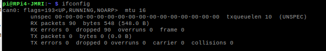
2. Common Issues & Resolutions
-
can0not found-
Confirm
dtoverlay=mcp2515-can0,oscillator=8000000,interrupt=25is in/boot/config.txt. -
Ensure these lines exist in
/etc/modules:
-
    spi-dev
    mcp251x
-
Reboot:
sudo reboot. -
Interface is down or errors on bring-up
-
Bring it up manually:
sudo ip link set can0 up type can bitrate 125000 -
Check kernel messages for clues:
dmesg | grep -i mcp251x
dmesg | grep -i spi
-
-
No traffic or garbled frames
-
Verify termination resistors: 120 Ω jumpers must be fitted at both ends of your CAN bus.
-
Inspect wiring and connectors for loose pins or mis-routing.
-
Use
candumpto sniff traffic:sudo apt install can-utils candump can0
-
- Next Steps
Once can0 is up and passing valid frames, move on to your JMRI or CDI configuration to map LCC Event IDs and throttle panels.
References
- Adding CAN to the Raspberry PI - provides information on selection of the MCP2515 board and information used in the design of RPi-CAN Card and Linux configuration.
- JMRI RaspberryPi as Access Point by Steve Todd provides details on the RPi image pre-configured for use with JMRI