Serial Menu
Table of contents
Table of contents
Introduction
The Node Card Firmware offers extensive support for managing and interacting with the LCC Fusion Cluster of LCC Fusion Node Card and I/O Cards. This functionality is accessible through a Serial Menu interface, providing a command-line style menu LCC Node administrators to perform various management tasks, test connectivity, and monitor device activity.
Accessing the Serial Menu
 To use the Serial Menu for managing the Node Card firmware:
- Connect the Node Card to your computer via USB.
- Open the Serial Menu from your development environment (e.g., Yet-Another-Terminal (YAT), Arduino IDE).
- Ensure the Serial Menu is set to the correct port and baud rate (115200 by default).
- To access the Main Menu, enter
min the Serial Menu’s input field.
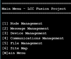
Main Menu Overview
 The Main Menu provides several options for interacting with the Node Card. Each menu item corresponds to a specific aspect of Node Card or Cluster management, as outlined below:
-
Node Management
- Accesses submenus to test devices, simulate input and output, and configure the Node card.
- Options include Display Pin Values for various I/O devices, Simulate I/O operations, and Test Node Card Connectivity with other components in the cluster.
- Provides Node Reboot and Up Time Display options.
2. Message Management
- Allows you to display messages (new-to-old or old-to-new), log messages to a file, and purge log files.
- Useful for reviewing communication logs and debugging connectivity or message handling issues within the cluster.
3. Device Management
- Displays the status of attached I/O devices to verify operational conditions and configurations.
4. Communications Management
- Provides tools to check network status, display Wi-Fi and Network settings, and configure or connect to Wi-Fi.
- Useful for establishing and troubleshooting network connections within the LCC Fusion Cluster.
5. File Management
- Offers file handling capabilities for reviewing logs, copying files, and managing file storage on the Node Card’s SD card.
- Options include listing, displaying, and purging files.
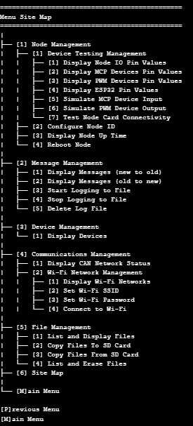
6. Site Map
- Useful quick navigation
- Visually outlines the menu structure and the corresponding command options, making it easy to find the function you need.
- The Site Map lists each primary menu item and its sub-options, providing a comprehensive overview of available commands.
Menu Details
| Title | Prompt | Description |
|---|---|---|
| Work with Node Information | [1] Device Testing Management | Opens the Hardware Testing submenu to test I/O, simulate input/output, and perform connectivity tests on GPIO, I²C, and CAN devices. |
| [2] Configure Node ID | Prompts for a new LCC Manufacturer’s Serial Number (last 3 bytes) and updates the Node’s ID. | |
| [3] Display Node Up Time | Shows system uptime in days, hours, minutes, and seconds. | |
| [4] Display Node CPU Load | Displays current CPU load percentage with a refresh option. | |
| [5] Display Node Free Memory Size | Displays current free heap size and the minimum-ever free heap watermark. | |
| [6] Display Node Bus Hub Voltages | Display current voltage levels of the Node Bus Hub 3V3 and 12V connections. | |
| [7] Reboot Node | Prompts for confirmation before restarting the ESP32. | |
| Work with Hardware Testing | [1] Display Node I/O Pin Values | Prints the current state (HIGH/LOW) of each Node Card I/O pin. |
| [2] Display MCP Devices Pin Values | Prints the state of each pin on connected MCP23017 devices. | |
| [3] Display PWM Devices Pin Values | Prints the state (ON/OFF) of each line on PCA9685 PWM devices. | |
| [4] Display ESP32 Pin Values | Prints the state of each GPIO pin on the ESP32. | |
| [5] Simulate MCP Device Input | Prompts for a device and pin number, then sets that input HIGH to simulate activity. | |
| [6] Simulate PWM Device Output | Prompts for a line number, then sets that output HIGH to simulate activity. | |
| [7] Test Node Card Connectivity | Guides through continuity tests for I²C, CAN and I/O, displaying success or error messages. | |
| Work with Messages | [1] Display Messages (new to old) | Lists stored messages from newest to oldest, page by page until “No more messages.” |
| [2] Display Messages (old to new) | Lists stored messages from oldest to newest. | |
| [3] Start Logging to File | Begins logging incoming messages to persistent storage on the SD card. | |
| [4] Stop Logging to File | Stops message logging to persistent storage. | |
| [5] Delete Log File | Deletes the stored message log file from persistent storage. | |
| Work with Devices | [1] Display Devices | Scans and lists all connected I²C devices (MCP23017, PCA9685), showing bus and address or “No devices found.” |
| Work with Communications | [1] Display CAN Network Status | Shows CAN bus statistics: processed, missed, discarded, lost, overruns for RX and processed, success, failed for TX, with refresh. |
| [2] Display Serial Connections | Shows number of Bluetooth and Web Serial clients and the Web Serial URL, or “not configured” messages. | |
| [3] Wi-Fi Network Management | Opens the Wi-Fi Management submenu. | |
| Work with Wi-Fi | [1] Display Wi-Fi Networks | Scans and lists available networks with SSID and signal strength. |
| [2] Set Wi-Fi SSID | Prompts for and stores the SSID to connect to. | |
| [3] Set Wi-Fi Password | Prompts for and stores the Wi-Fi password. | |
| [4] Connect to Wi-Fi | Attempts to connect using stored credentials and displays SSID, IP address, and signal strength. | |
| Work with Files | [1] List and Display Files | Lists available files on SPIFFS (and SD card), prompts for selection, and displays the file’s contents. |
| [2] Copy Files To SD Card | Prompts for a file and writes it from SPIFFS to the SD card. | |
| [3] Copy Files From SD Card | Prompts for a file and writes it from the SD card to SPIFFS. | |
| [4] List and Erase Files | Lists files and prompts to delete the selected file from SPIFFS or SD card. |
Using the Menu System
Once connected to the Serial Menu, navigate through the menus by typing the corresponding number or letter for each command. For instance, to access Node Management, type 1 and press Enter. Similarly, to test the Node Card’s CAN connectivity, navigate to the appropriate submenu and follow the prompts.
This command-driven interface enables efficient testing, configuration, and monitoring without requiring direct programming changes, making it an essential tool for maintaining and troubleshooting the LCC Fusion Cluster.