Signal Application Scenario Configuration Guide
Table of contents
Table of contents
Application Scenarios
BOD Card Configuration
 Using a CDI configuration tool, open the BOD Card(s) segment and update as follows:
- Configure the card’s information section and the communications
COMM BUSandCOMM ADDRfields to match the corresponding selections on the BOD Card (PCB). - Refer to the
Linetab for the line connected to the track block. The default value for theON Event IDwill be used for setting up the signal masts aspect. If available in the configuration tool, use theCopybutton to copy the Event ID to the clipboard for use later.
Signal Mast Configuration
-
Using a CDI configuration tool, open the Signal Masts segment and update as follows:
-
Click on the
Card 1andMast 1tabs. For this example, the card 1 is connected to a Signal Masts Breakout Board connected to the mast. -
Update the
Card Information ConfigurationandCard Communications Configurationfields. -
Update the
Rule to Aspect Mapping Configuratonas follows: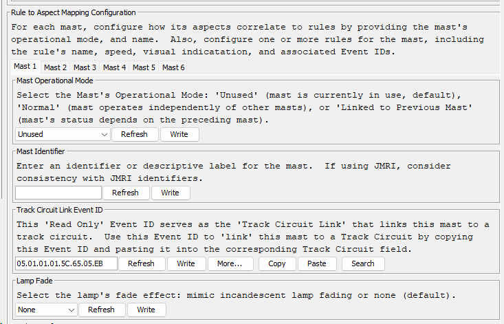
| Field | Value | Description |
|---|---|---|
| Mast Operational Mode | Normal |
Setting indicates the mast enabled in a nomal mode, not linked to any other masts. |
| Mast Identifier | Enter a value to identify the task. | |
| Track Circuit Link Event ID | Configuring a track circuit is not needed for this example. | |
| Lamp Fade | None |
Setting indicates no fading of the lamp |
- Configure the ‘Stop’ rule by configurating the
Rule 1tab’s fields as shown to the right and detailed below:
| Field | Value | Description |
|---|---|---|
| Mast Operational Mode | Normal |
Setting indicates the mast enabled in a nomal mode, not linked to any other masts. |
| Mast Identifier | Enter a value to identify the task. | |
| Track Circuit Link Event ID | Configuring a track circuit is not needed for this example. | |
| Lamp Fade | None |
Setting indicates no fading of the lamp |
| Rules Configuration | Rule 1(tab) |
Configure the the 1st rule |
| Rule Name | 0-Stop |
Selection identifies the rule being configured |
| Rule Track Speed | Stop |
Selection identifies the speed for the track. |
| Rule’s Aspect Indicator | R/R - Stop before Signal |
Selection identifies the aspect to be shown. |
| Set Aspect Event ID | The Event ID to set the aspect. Used with Logics and Conditionals for setting the aspect. | |
| Aspect Set Event ID | Not used. | |
| Aspect Cleared Event ID | Not used. | |
| Lamps Configuration | Lamp 1 (tab) |
Selection identifies configuration for the first lamp. |
| Lamp Selection | LED_1 |
Select the LED number associated with the lamp associated the wired mast. |
| Lamp Phase | Steady |
Selection indicates the lamp is to remain steadyly lite. |
| Lamp Brightness | 50 |
Selection indicates the lamp is be set a 50% brightness, a good starting point. |
| Lamp Glow Effect Duration | Selection identifies a normal glow of the lamp. |
- Configure the ‘Clear’ rule by configurating the
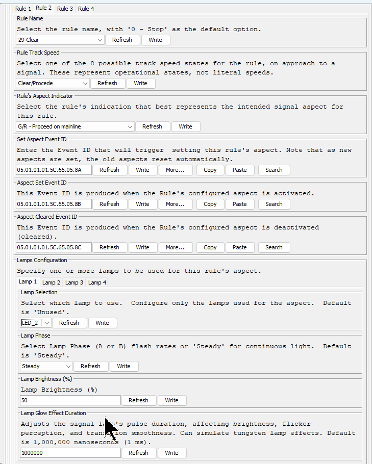
Rule 2tab’s fields as shown in detailed below:
![]()
| Field | Value | Description |
|---|---|---|
| Rules Configuration | Rule 2(tab) |
Configure the the 2nd rule (for normal speed) |
| Rule Name | 29-Clear |
Selection identifies the rule being configured |
| Track Speed | Clear |
Selection identifies the speed for the track. |
| Aspect Indicator | G/R - Proceed on Mainline |
Selection identifies the aspect to be shown for the desired speed. |
| Set Aspect Event ID | The Event ID to set the aspect. Used with Logics and Conditionals for setting the aspect. | |
| Aspect Set Event ID | Not used. | |
| Aspect Cleared Event ID | Not used. | |
| Lamps Configuration | Lamp 1 (tab) |
Selection identifies configuration for the first lamp. |
| Lamp Selection | LED_1 |
Select the LED number associated with the lamp associated the wired mast. |
| Lamp Phase | Steady |
Selection indicates the lamp is to remain steadyly lite. |
| Lamp Brightness | 50 |
Selection indicates the lamp is be set a 50% brightness, a good starting point. |
| Lamp Glow Effect Duration | Selection identifies a normal glow of the lamp. |
Logics and Conditionals Configuration
For this simple signaling example, we can use just one Logic statement to configure the mast to show the correct aspects for stop or clear based on the track occupancy downstream.
The logic statement looks like this: IF (Block is Occupied) THEN Set Aspect to Stop ELSE Set Aspect to Clear.
- Since only one logic statement is needed, for the Logic Group indicate that the logic is that last one for the group.
- For the conditional, define use a single Condition (V1) configured to check for the ‘occupied’ Event ID what would be produced by the BOD Card’s configuration for the connected track block that is downstream of the mast.
- For the True action, configure the Event ID for setting the Mast Stop aspect, which was previously defined by configuring the Masts
Rule 1. - For the Flase action, configure the Event ID for setting the Mast Clear aspect, which was previously defined by configuring the Masts
Rule 2. - For both actions, configure the action to be performed immediately and to stop processing after the Event ID is sent.
Below are the detailed steps for configuring this example:
- Using a CDI configuration tool, open the Logics and Conditionals segment and update as follows:
- Click on the
Logic 1tab. - Set the group processing information and define the conditional as follow:
+
| Field | Value | Description |
|---|---|---|
| Description | Main Line Signal Control | A label describing the purpose of the logic, such as managing the main line signal. |
| Group Functionality of Logic | Last... |
Setting indicates that this is the ‘Last’ logic statement in a group. In this example, a group of only 1 logic. All other logics in the table will default to Blocked and will be ignored (not used). |
| Condition 1 Configuration | The following fields define the logic conditional’s first condition, Condition 1. | |
| Condition 1 Source | Event ID |
Identifies the source for the condition. This Logic’s conditional uses anEvent ID (block’s occupied status) to determine its state for true/false. The Event ID from the BOD Card configuration is specified below. |
| Condition’s Trigger | When Condition's Event ID or Speed Changes |
Selection indicates that the condition’s is triggered by a change in the Event ID which occurs with the BOD Card detects a track occupancy change. |
| Condition’s Track Circuit Speed | This is only used condition’s souce is a Track Circuit (Speed from Track Circuit #). |
|
| Condition’s True Event ID | Enter an Event ID that triggers this condition to be true. Use the On Event ID value configured for the BOD Card’s block that is produced when the downstream block is occupied. If possible, simply copy and paste the Event ID found in the BOD Card Line associated with the block. |
|
| Condition’s False Event ID | Enter an Event ID that triggers this Condition to be false. Use the Off Event ID value configured for the BOD Card’s block that is produced when the downstream block is cleared (not occupied). If possible, simply copy and paste the Event ID found in the BOD Card Line associated with the block. |
|
| Logic Operations | Condition 1 Only |
Indicates how the Logic Conditional is be processed using only Condition 1. |
Configuration of
Condition 2is not required since the conditional only needs one Condition defined.
-
Configure how the Logic is too be processed when the conditional is true and when it is false. In both case, since there is only one logic in the group the processing should exit the group and that both actions should be processed immediately.
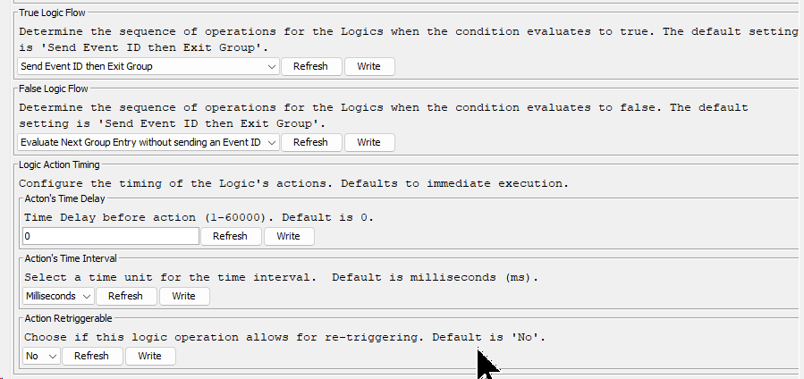
| Field | Value | Description |
|---|---|---|
| Logic’s Flow When True | Send then Exit Group |
Setting indicates that processing of the logic group terminates after handling the logic’s true condition. No other logics are necessary for setting the signal mast aspects. |
| Logic’s Flow When False | Send then Exit Group |
Setting indicates that processing of the logics group terminates after handling the logic’s false condition. No other logics are necessary for setting the signal mast aspects. |
| Action’s Time Delay | 0 |
Setting indicates that the logic’s actions should take place immediately, causing the aspect to be set immediately. |
| Action’s Time Interval | Not used since the Timing is set to 0. |
|
| Action Retriggerable | No |
Setting indicates the logic’s actions can NOT be retriggered again after completion. |
-
Configure two actions, one for when the conditional is true (track block is occupied) and one when the conditional is false. In both cases, Event IDs are sent to set the appropriate aspect for the mast.
| Field | Value | Description |
|---|---|---|
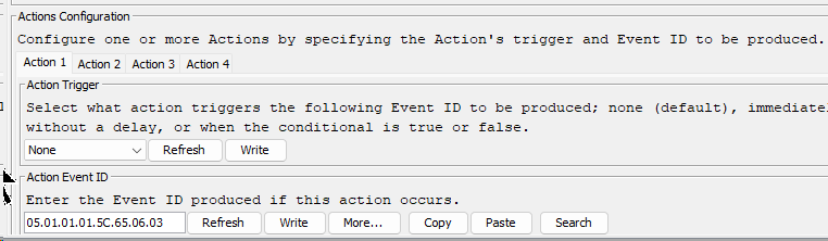
| Action(s) Configuration | Action 1 (tab) |
The first action configured will set the mast aspect for the Rule Name 0-Stop. |
| Action Trigger | Immediately if True |
Selection indicates the action is to occur immediately if the conditional is True (i.e. the block is occupied). The actual action produces the following Event ID. |
| Action Event ID | 05.01.01.01.5C.65.06.03 |
Enter the Set Aspect Event ID from Mast 1, Rule 1 which is configured for 0-Stop rule with an aspect for a Stop speed. |
| Action(s) Configuration | Action 2 (tab) |
The second action configured will set the mast aspect for the Rule Name 29-Clear. |
| Action Trigger | Immediately if False |
Selection indicates the action is to occur immediately if the conditional is False (i.e. the block is unoccupied). The actual action produces the following Event ID. |
| Action Event ID | 05.01.01.01.5C.65.06.02 |
Enter the Set Aspect Event ID from Mast 1, Rule 2 which is configured for 29-Clear rule with an aspect for Normal speed. |