Signal Planning Guide
Table of contents
Table of contents
Introduction
Signals on a model railroad convey operational instructions to train operators by presenting specific signal aspects at defined locations on the layout. Effective signal planning focuses on what information must be conveyed and under what conditions, rather than on the physical construction of signal masts or lamps.
In the LCC Fusion Project, signal planning is centered on:
- Defining the signal aspects required at each location
- Determining the downstream conditions that influence those aspects
- Structuring logic statements that evaluate conditions and set aspects accordingly
This guide focuses on planning signal behavior using logic statements and signal groups. Physical implementation details - such as mast wiring, lamp connections, and PWM channel assignment - are intentionally out of scope.
Signal planning defines what instructions are shown and when they change. Hardware and configuration define how those instructions are displayed.
Planning Context
Signal planning occurs after track, turnout, and block planning, when you understand:
- Where trains may travel
- Where routes diverge or converge
- Which blocks must be protected
- Which downstream conditions influence train movement
Planning signal behavior involves deciding:
- Which aspects are required at each mast
- How many downstream elements influence each signal
- How logic statements should be ordered to enforce safe operation
- When logic processing should stop or continue within a signal group
Only after signal behavior is planned should physical signal hardware and lamp layouts be selected.
Relationship to Logic and Configuration
Signals in LCC Fusion are controlled by logic groups, each consisting of one or more logic statements. During planning, logic is expressed using an if-then-else structure to clearly describe behavior without committing to configuration details.
This planning approach allows:
- Complex signal behavior to be reasoned about before configuration
- Incremental refinement of logic without hardware changes
- Consistent behavior across different signal hardware types
Terminology
Below is a set of terms used in both planning and configuring of signal aspects:
-
Logic Statement: for planning purposes, a logic statement is in the form of a typical if-then-else statement as shown here:
IF
conditionalTHENaction(s) for true conditionsELSEactions for false conditionsExample: 1. If Block is Occupied, Then Set aspect to
StopandExitElse Set aspect toClearandContinue.Explanation:
- `1.`: indicates this is the first logic statement in the group. - `Block is Occupied`: is the conditional, consisting of a single variable to be checked for true or false. Up to two variables can be specified, separated by a logic operator like `OR` and `AND` - `Set aspect to Stop` is the action that to be performed when the conditional is true. - `Continue` determines that the processing of additional logic statements should continue. If this is the last (or only) logic statement in the group, then processing of the group will stop and proceed with the next logic group. - `Set aspect to Clear` is the action to be performed when the conditional is false. -
Conditionals: condition(s) to be evaluated, resulting in either true or false. Conditionals contain either one or two variables. When two variables are define, a logic operator is used;
V1 and V2,V1 OR V2,V1 Only, etc. -
Actions: is what happens when the conditional is true or false. Typically the action sets the aspect or does nothing.
-
Logic Group: represents a collection of logic configurations accessible via the CDI tool in the Logics and Conditionals section.
- Planning example:
- If Block is Occupied, Then Set aspect to
StopandExitElseContinue. - If Downstream Mast’s Track Circuit indicates
Stop, Then Set aspect toApproachandContinueElse Set aspect toClearandContinue.
- If Block is Occupied, Then Set aspect to
- Planning example:
-
Logic Processing determines what happens after the a logic statement is processed,
Exitto stop processing the logic statements in the group, orContinueto continue with the next logic statement (e.g. additional conditions need to be evaluated and aspects set). Note that processing the last logic statement in the group will automatically exit the group upon completion. -
Track Circuit: Track Circuits report the downstream track speed as shown by a mast linked to the track, simplifying the number of conditions that need checking and are particularly useful when dealing with downstream masts. During configuration, a track circuit is used as a variable in the conditions. For example, when the downstream signal aspect is reporting a stop speed, the current mast typically would show an approach speed.
- Planning example: If Downstream Mast’s Track Circuit indicates
Stop, Then Set aspect toApproachandContinueElse Set aspect toClearandContinue.
- Planning example: If Downstream Mast’s Track Circuit indicates
Signal Mast Aspect Usage Examples
| Aspects | Mast Name | Signal Type | Purpose/Use | Example Triggers |
|---|---|---|---|---|
| Caution, Clear | Mainline Distance Signal | Two-Aspect Signal | Provide advance warning of mainline signal status. | Next Block Occupied or Clear |
| Stop | Yard Entry Mast | Single-Aspect Signal | Signal yard entry restrictions. | Yard Block Occupied |
| Stop, Approach, Clear | Crossover Signal Mast 3 | Three-Aspect Signal | Indicate safe crossover alignment. | Turnout Aligned or Block Status |
| Stop, Clear | Mainline Signal Mast 1 | Two-Aspect Signal | Control train movement on a mainline. | Block Occupied or Turnout Misaligned |
| Stop, Clear | Yard Exit Mast 6 | Two-Aspect Signal | Signal safe yard exit onto mainline. | Mainline Block Status |
| Stop, Diverging Clear, Clear | Junction Mast A | Three-Aspect Signal | Control train movement at a turnout junction. | Turnout Alignment and Block Status |
| Stop, Restrict, Clear | Siding Signal Mast 2 | Three-Aspect Signal | Indicate siding availability. | Siding and Mainline Block Status |
| Stop, Restrict, Approach, Advance Approach, Clear | Mainline Mast 4 | Multi-Aspect Signal | Provide multiple aspects for mainline operations. | Turnout and Block Status |
Signal Mast Aspect Configuration Summary
The following table is provided to assist in simplifying the configuration of signal mast aspects. The configurations are listed based on the number of signal aspects to be set (heads and lamps) and what is influences the aspect downstream of the signal (blocks, turnouts, masts).
To further simplify the planning:
- only three aspects are define;
Stop,Approach, andClear. - check for all conditions that set the aspect to
Stop, followed by conditions forApproach, and finallyClear. - even thought configuring aspects requires configuring the indications, the setting of the lamps is not defined below since that varies by the aspect rules and signal head type.
- utilize the minimum necessary number of logic statements.
- track circuits are used to check for downstream track speeds
Note that up to 4 actions can be executed for true and false conditions, allowing for a tumble-down to be configured for setting up to 4 aspects. For example, when configuring the first signal located at the beginning of a set of blocks between sidings (headblock), configure multiple actions for this signal where each action sets the same aspect downstream signals, thus creating a tumple-down of the signals being set (all appear the same).
The use of Exit and Continue within the logic statements’ actions signals whether the logic processing for that group should cease (‘Exit’) or proceed to evaluate the next logic statement (‘Continue’). Generally, once the appropriate aspect is displayed based on the evaluated conditions, the logic processing for that group concludes.
Ordering Conditionals: When crafting a logic statement for a signal, it is standard practice to first assess conditions that necessitate the most restrictive track speed (e.g., Stop), followed by conditions for intermediate speeds (e.g., Approach), and lastly, conditions allowing the least restrictive speeds (e.g., Clear).
| Signal Mast Configuration | Downstream Elements | Logic Group (one or more logic statements) | Visual |
|---|---|---|---|
| Single 2-Lamp Head | 1 Block, 1 Masts, 0 Turnouts | 1. If Block is Occupied, Then Set aspect to Stop and Continue Else Set aspect to Clear and Continue. |
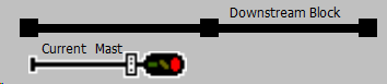 |
| Single 3-Lamp Head | 1 Block, 2 Mast, 0 Turnouts | 1. If Block is Occupied, Then Set aspect to Stop and ExitElse Continue. 2. If Downstream Mast shows Stop, Then Set aspect to Approach and Continue Else Set aspect to Clearand Continue. |
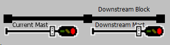 |
| 3-Lamp Head over 2-Lamp Head | 3 Blocks, 3 Masts, 1 Turnout | 1. If Turnout Block is Occupied, Then Set Upper Head aspect to Stop, Lower Head aspect to Stop, and Exit Else Continue.2. If Turnout is Thrown, Then Set Upper Head to Stop and Continue Else Continue3. If Downstream Mast shows NOT Clear Then Set Upper Head aspect to Approach and Continue Else Set Upper Head aspect to Clear and Continue.4. If Turnout is Closed OR Divergent Mast shows NOT Clear, Then Set Lower Head aspect to Stop and Continue Else Set Lower Head aspect to Clear and Continue |
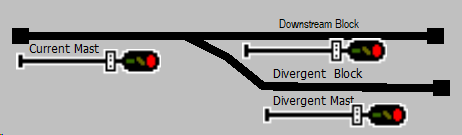 |
| 3-Lamp Head over 3-Lamp Head | 2 Blocks, 2 Masts, 1 Turnout | 1. If Turnout is Diverging, Then Upper Head Red, Lower Head Green for Diverging Route; 2. If First Block is Occupied, Then Upper Head Red, Lower Head Yellow; 3. Else Upper Head Green, Lower Head Green; |
|
| 2-Lamp Head over 2-Lamp Head | 1 Block, 1 Mast, 1 Turnout (Diverging) | 1. If Turnout is Diverging, Then Upper Head Red, Lower Head Green; 2. If Block is Occupied, Then Both Heads Red; 3. Else Both Heads Green; |
|
| Twin 3-Lamp Heads (Side by Side) | 2 Blocks, 2 Masts, 2 Turnouts | 1. If Either Turnout is Diverging, Then Corresponding Head Shows Yellow; 2. If Either Block is Occupied, Then Corresponding Head Shows Red; 3. Else Both Heads Show Green; |
|
| 2-Lamp Head over 3-Lamp Head | 1 Block, 2 Masts, 1 Turnout | 1. If Turnout is Diverging, Then Upper Head Green, Lower Head Yellow; 2. If Block is Occupied, Then Upper Head Red, Lower Head Red; 3. Else Upper Head Green, Lower Head Green; |
|
| Dwarf Signal, 3-Lamp | 1 Block, 0 Masts, 1 Turnout (Diverging) | 1. If Turnout is Diverging And Block is Occupied, Then Display Red; 2. If Turnout is Diverging, Then Display Yellow; 3. Else Display Green; |
|
| Vertical Stack of 3-Lamp Heads | 3 Blocks, 3 Masts, Multiple Turnouts | 1. If Any Turnout is Diverging, Then Corresponding Head Red; 2. If Any Block is Occupied, Then Corresponding Head Yellow; 3. Else All Heads Green; |
|
| 4-Lamp Head (Single or Multiple) | Specialty areas like speed-controlled zones | 1. If Speed Restriction in Place, Then Display Aspect According to Restriction; 2. If Block Ahead is Occupied, Then Display Yellow; 3. Else Display Green; |
References
- Planner’s Guides
- Getting Started
- Node Clusters
- Scaling with PODs
- Node Power Planning Guide
- Wired Node-to-Node Planning Guide
- Wireless Node-to-Node Planning Guide
- Configurator’s Guides
- Educational Media – Understanding LCC Fusion – A Clear On-Ramp into LCC-Based Layout Automation – LCC Fusion Podcast – Fusion Hardware Architecture Overview – LCC Fusion Podcast – Cards & Node Basics