Sound Card Assembly Guide
Table of contents
Table of contents
- Sound Card Assembly Guide
- Introduction
- Assembly and Component Placement
- Tools Required
- Safety Precautions
- Testing and Verification
- Component Orientation: the IC’s are correctly oriented according to the PCB silkscreen or schematic.
- If no sound: verify I²S header orientation, amplifier IC soldering, speaker wiring/polarity, and the 5 VDC audio rail.
- Visual Inspection
- Connectivity Testing
- Functional Testing
- Provisioning the Card
- Troubleshooting
- Appendences
Introduction
See the How to Use Assembly Guides for detailed instructions.
The Sound Card is a key component in the LCC Fusion Node system, designed to bring audio capabilities to model train layouts and other automation projects. By utilizing up to four low-cost MP3 players, the Sound Card enables the simultaneous playback of multiple sounds, triggered through LCC (Layout Command Control) Events. This feature makes it ideal for creating automated sound effects such as ambient noises, train sounds, and announcements, enhancing the realism of your layout.
The Sound Card works by interfacing with DFPlayer modules to play preloaded MP3 files in response to LCC events. Sounds can be played, stopped, or looped based on various conditions or triggers within the layout automation system. Each of the four DFPlayer modules can handle a separate audio stream, allowing you to control different sound sources at the same time.
The Sound Card integrates up to four DFPlayer modules, each capable of converting MP3 files into an audio stream. These audio streams are output to speakers, making the Sound Card a versatile solution for playing sound effects in your layout.
Key Features
- Supports up to four DFPlayer MP3 modules, allowing simultaneous playback of different sound effects.
- Triggered by LCC Events: The playback of MP3 files is controlled through LCC commands, enabling dynamic interaction with the layout.
- Integration with the Digital I/O Breakout Board: Audio streams are routed through the Digital I/O Breakout Board and can be connected to multiple speakers.
- Versatile Audio Control: Each MP3 module can handle separate audio files, making it easy to assign unique sounds to different events or areas of your layout.
Use Cases
- Train Whistles and Horns: Automatically play train-related sounds when the LCC system detects certain conditions, such as a train approaching a station or a signal changing.
- Station Announcements: Play station announcements when triggered by events like train arrival or departure.
- Ambient Sounds: Set up background sounds (such as birds chirping or city noises) that loop in specific areas of the layout.
System Overview:
The Sound Card interfaces with the LCC Fusion Node Card, which handles the LCC Events. Once an event is triggered (such as a train passing a sensor or a control panel command), the corresponding MP3 file is played on one of the four connected DFPlayer modules. The output from the DFPlayers is routed through the Digital I/O Breakout Board to speakers located across the layout, ensuring immersive sound throughout the environment.
flowchart LR;
s((speakers));
subgraph layout ["Train Layout"];
direction LR;
n[Node Card] --> c["Sound Card<br/>(DF Players)"];
c --> bb[Digital I/O  Breakout Board] --> |"Audio Stream<br/> (wires)"| s;
c --> |"Audo Stream <br/> (wires)"| s;
end;
classDef lSalmonStyle fill:#FFA07A,stroke:#333,stroke-width:2px,font-size:24px;
class c lSalmonStyle;
classDef lightGrayStyle fill:#d3d3d3,stroke:#333,stroke-width:2px,font-size:24px;
class layout lightGrayStyle;
Assembly and Component Placement
This section combines both the component specifications and the assembly instructions to ensure a smooth assembly process. Below is a comprehensive list of components, their placement on the PCB, and orientation details to assist you during assembly.
High-Level Steps for Assembly:
- PCB for the card can be ordered from any PCB fabricator using these Gerber Files.
- Clean PCB with alcohol to remove residue. See Cleaning_PCB for details.
- See also: Soldering Tips
- PCB Components - listing of components used for PCB assembly
- PCB Parts - listing of parts used for PCB assembly
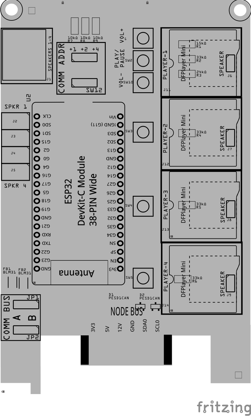
Below is a list of the PCB components used for this card (see diagram before reference):
![]()
![]()
| Component Identifier | Count | Type | Value/Description | Package | Purpose | Orientation |
|---|---|---|---|---|---|---|
| Diodes | ||||||
| D1, D2 | 2 | ESD Diode | PESD1CAN | SOT-23 SMD | I2C data bus electrostatic discharge (ESD) protection | Fits only one way |
| Filters & Noise Suppression | ||||||
| FB1, FB2 | 2 | Ferrite Bead | BLM31PG121SN1L | 1206 SMD | I2C Network Bus Data Line Noise Suppression | None |
| Connectors | ||||||
| J1 | 1 | RJ45 Socket | 8P8C | PTH | Speaker connections | Fits only one way |
| J2-J5 | 4 | Spring Terminal | 8-Pin, 2.54mm | PTH | Speaker connections | None |
| J6-J9 | 4 | Male Headers | 2-Pin, 2.54mm | PTH | Earphone/Speaker connections for testing | None |
| J11-J14 | 8 | Female Headers or Male Pins | 8-Pin, 2.54mm | PTH | Socktet mount for DFRobots DFPlayer Mini (or compatible MP3-TF-16P player) to play files from mini-SD card | None |
| Resistors | ||||||
| R1 | 1 | Resistor | 15kΩ | 1206 SMD | Limits the current to the Tact button and MP3 player (volume+ long press) | None |
| R2, R4-7 | 5 | Resistor | 33kΩ | 1206 SMD | Limits the current to the Tact button and MP3 player (play/pause function) | None |
| R3 | 1 | Resistor | 24kΩ | 1206 SMD | Limits the current to the Tact button and MP3 player (volume- long press) | None |
| R7-R9 | 3 | Resistor | 10kΩ | 1206 SMD | Limits the current to SW1 and ESP32 for the I2C address | None |
| R10 | 1 | Resistor | 10k Ω | 1206 SMD | Voltage Divider (high/low ends) | None |
| R11 | 1 | Resistor | 2.7kΩ | 1206 SMD | Voltage Divider (high/low ends) | None |
| Selectors & Indicators | ||||||
| JP1, JP2 | 2 | Male Header | 3P, 0.1” spacing | PTH | Used to set the I2C bus to be used (A or B). These are the ESP32 hardware buses used for serial communications (0 or 1). | None |
| SH1, SH2 | 2 | Jumper Cap | Jumper Cap (2.54mm) | 2.54mm | Used with I2C Bus selection | None |
| SW1 | 1 | DIP / Slide Switch | 3P, 2.54mm | PTH | Sets I2C address offset (0-7), added to base address of ESP32 (0x10). | Position so switch so ON is towards PCB top edge |
| SW2-SW6 | 5 | Tact Button | N/A | SMD | Controls for play/pause, and volume + / - (player 1) | Fits only one way |
| ICs | ||||||
| U1 | 1 | ESP32 Module | ESP32 DevKitC | DevKitC | Processes I2C text messages from the Node Card and sends player commands via UART | Position USB connection to PCB right edge |
| Storage | 1 per player | MicroSD Card | N/A | N/A | Stores MP3 files to play (one per player). Filenames must be formatted as 000nn |
N/A |
Tools Required
Safety Precautions
- See Safety Precautions.
Testing and Verification
The following test and verifications of the card should be performed after a through inspection of the card’s soldering. Check all of the PTH component pins and SMD pads. Make sure there are no solder bridges between pins and pads.
Visual Inspection
- Solder Joint Inspection: Use a magnifying glass or a microscope to inspect solder joints. Look for cold solder joints, insufficient or excessive solder, or any shorts between pads.
-
Component Orientation: the IC’s are correctly oriented according to the PCB silkscreen or schematic.
Power-Up Tests
- Seat the Sound Card Insert the Sound Card into a tested LCC Fusion Node Bus Hub (leave speakers disconnected).
- Load firmware & insert the ESP32
- Flash the Sound Card firmware onto an ESP32 DevKit-C.
- Insert the DevKit-C into the Sound Card’s socket.
- **Power the Sound Card **
- Power the Node Bus Hub using either a tested Node Card or a Power-CAN Card.
- Quickly check for hot components; power off if anything heats abnormally.
- Self-test the Sound Card
- Attach and open a serial monitor at 115200 to the Sound Card’s ESP32 (DevKit-C on the Sound Card, not the Node Card).
- From a serial monitor, enter the command (letter)
Tto start the firmware’s self-test, then review the results.- Messages may appear on BT, OLED, or the attached serial monitor.
- See: PCB Self Testing.
- What you do: simply watch the summary—no meters or scopes required.
- Pass indicators: each tested group reports a success status.
- If any group fails: power down, re-seat the DevKit-C and Sound Card, inspect solder on the affected header/IC, and re-run.
-
Tests Performed
-
Sound Card Pins Test (automatic)
After powering the Sound Card, the firmware automatically performs a Pin Self-Test (PST) to confirm that key communication lines are correctly wired and behaving as expected. These checks require the Sound Card to be installed in a powered Node Bus Hub, since the Hub provides the regulated 3.3 VDC and 5 VDC rails, I²C pull-ups, and CAN backbone termination used during testing.
Interface Verification Summary
- I²C Bus
- Pins:
SDA,SCL - Briefly exercised as open-drain I/O to verify the Node Bus Hub’s pull-ups and confirm that both lines idle HIGH.
- Confirms line integrity and that neither SDA nor SCL is shorted or stuck LOW.
- If the Hub is not connected and power is provided only through the USB port, the PST runs quietly and treats missing pull-ups as normal for bench testing.
- Pins:
- UART Links
- Pins: Four RX/TX pairs connecting the ESP32 to DFPlayer modules.
RXpins are tested as Inputs (in gentle mode — no pulldown applied).TXpins are tested as Outputs (idle HIGH).
- Verifies that each UART line is electrically intact and not shorted, even when DFPlayers are not installed.
- Pins: Four RX/TX pairs connecting the ESP32 to DFPlayer modules.
- I²C Bus
-
Speaker Path Test (audible)
- Plays a short test-tone sequence over I²S → MAX98357A → speaker with gentle fade-in/out.
- What you do:
- Connect one speaker to the first speaker connector.
- Run the Speaker Test and listen for two distinct tones (e.g., higher tone then lower).
- For multiple amps/speakers, move the connector to each speaker connector and repeat.
- Expected result: clear, non-distorted tones at moderate volume; no pops/crackles at start/stop.
-
If no sound: verify I²S header orientation, amplifier IC soldering, speaker wiring/polarity, and the 5 VDC audio rail.
Sound Output Testing (Using Card Monitor Board)
-
If you connect the Sound Card’s RJ45 output to the Card Monitor Board, the LEDs will show faint flicker or shimmer in response to sound output across all eight lines.
This test is optional but can confirm that the ESP32, amplifier, and output drivers are active before connecting speakers.
| Lines | What You Should See | How to Read It |
| ——— | ———————————————————- | ———————————————————— |
| L1–L8 | Dim flicker or variable brightness when audio is playing | LEDs react only to the positive half of the AC audio signal. You’ll see subtle glow/flicker that follows loudness or rhythm. If all remain dark, the card is silent or inactive. |
—
Jumper / Ground Setup
| Item | Setting / Action | Purpose | | ————————– | —————————————— | ———————————————————— | | JP1 (L8: GND / OUTPUT) | OUTPUT | Select OUTUT since the Sound Card does not provide a GND line on the RJ45. | | J1 (PWR BUS GND) | Connect to the Sound Card’s supply GND | Provides the only return path so the LEDs can light. Must share the same power ground as the Sound Card (Node Bus Hub) |
Notes:
- The Sound Card does not supply GND on the RJ45 audio lines. You must connect J1 GND to the Sound Card’s power-supply ground (common return).
- LEDs are activity indicators only—they do not represent tone, volume, or fidelity.
- LEDs light only on the positive half-cycles, so flicker may be faint or uneven—this is normal.
- Speaker pair mapping: adjacent lines form pairs (e.g., L1/L2, L3/L4, L5/L6, L7/L8). In stereo builds, you’ll typically see different flicker patterns between left/right pairs.
- For meaningful audio testing (quality, channel balance), use speakers.
Tip: Use this LED check just to confirm the Sound Card is alive before you hook up speakers; faint flicker is expected.
Visual Inspection
-
Initial Check: Examine the board for any obvious issues like missing components, solder bridges, or components that are misaligned or not fully seated.
-
Solder Joint Inspection: Use a magnifying glass or a microscope to inspect solder joints. Look for cold solder joints, insufficient or excessive solder, or any shorts between pads.
-
Component Orientation: the IC’s are correctly oriented according to the PCB silkscreen or schematic.
Connectivity Testing
- Continuity Check: Use a multimeter in continuity mode to check for shorts between power rails and ground, and to ensure there are no open circuits in critical connections.
Functional Testing
I2C Verification
- Verify that the I2C connection between the LCC Fusion Node Card and theI/O Card work. See Testing I2C Cards for details on how to test the I2C for a I2C enabled card.
MP3 Player Verification
After validating the LCC Fusion Node Card can connect with the I/O card, test each of the MP3 players as follows:
Provisioning the Card
- See Provisioning a Card.
Troubleshooting
- See I2C Trouble Shooting.
Appendences
PCB Specifications
The card has the following:
![]()
| Characteristic | Value |
|---|---|
| MP4 Players 1 | 1-4 |
| # Speakers 2 | 1-4 |
| Max MP3 per player | 100 |
- Requires a mini MP3 player. Supported players are the DFRobots DFPlayer Mini and compatible (MP3-TF-16P player)
- 4 watts @ 4-8 Ω
How It Works
The following outlines the flow of activity for the Sound Card:
flowchart LR;
  network["LCC Network"];
  cdi[("CDI Data")];
  fNodeFw("Firmware<br/>(ESP32)");
  fIoFw("Firmware<br/>(ESP32)");
  cs("Communications<br>Bus/Address");

  p["DF Players (4x)<br/>(converts mp4 to audio)"];
  sp1(("Speakers"));
  sp2(("Speakers"));
  sd[("SD Reader")];

  subgraph layout ["Train Layout"];
    direction LR;
    subgraph hub ["Node Bus Hub"]
      subgraph fIoCard ["Sound Card (16x)"];
        direction LR;
        fIoFw -->|"DF Player cmds<br/>(UART Serial Comm)"| p;
        sd -->|".mp4 file"| p;
        cs --> fIoFw;
      end
      subgraph fNodeCard ["Node Card"];
        direction LR;
        cdi --> |"Config"| fNodeFw;
      end
    end
    subgraph fIoBb ["Digital I/O<br/>Breakout Board"];
      direction LR;
    end
    fNodeFw --> |"I2C Serial Text Command<br>(cmd, player#, file#, vol%)"| fIoFw;
    network --> |"LCC Events<br/>(cable/WiFi/Now)"| fNodeFw;
    p --> |"Sound Stream<br/>(cable)"| fIoBb;
    fIoBb --> |"Sound Stream<br/>(wire)"| sp2;
    p --> |"Sound Stream<br/>(wire)"| sp1;
  end

  classDef blueStyle fill:#ADD8E6,stroke:#333,stroke-width:2px,font-size:24px;
  class fNodeCard blueStyle;
  classDef cyanStyle fill:#00FFFF,stroke:#333,stroke-width:2px,font-size:24px;
  class fIoCard cyanStyle;
  classDef lSalmonStyle fill:#FFA07A,stroke:#333,stroke-width:2px,font-size:24px;
  class fHubBb,fIoBb lSalmonStyle;
  classDef lightGrayStyle fill:#d3d3d3,stroke:#333,stroke-width:2px,font-size:24px;
  class layout lightGrayStyle;
-
Activity starts with an LCC Event sound related event being received by an LCC Fusion Node Card (firmware)
-
The LCC Node uses the Sound Card’s CDI configuration information to determine the I2C address of the card
-
A unique text message is sent to the Sound Card via I2C communications. The text message indicates one of the following:
-
play a specific mp3 file at the specified volume from a specific player (1-4). MP3 files are identified by their relative file number (0001xxx.mp3, 0002yyyy.mp3, etc.)
-
loop a specific MP3 file continuously
-
pause playing the current MP3 file on a specific player device
-
reset causes the MP3 players saved setting to be reset (setting are saved by default to NVS)
-
-
The Sound Card’s ESP32 devices processes the message and uses UART serial communications to connect to the specified MP3 device and sends MP3 commands to the player (play/pause, file #, and volume level)
-
MP3 player device plays/pauses the MP3. MP3 files are loaded from micro-SD card inserted in the player’s SD card reader.
Connections
| Component Designator | Connector Label | Connector Type | Connection Number | Description |
|---|---|---|---|---|
| J1 | SPEAKERS 1-4 | RJ45 Socket | 1/2, 3/4, 5/6, 7/8 | Pairs of connections to 4 speakers |
| J2, J3, J4, J5 | SPKR 1 - SPKR4 | JST XH, Spring Terminal | n/a | Pairs of connections to 4 speakers |
| J6, J7, J8, J9 | SPEAKER | Male Header | n/a | Connection to player’s speaker |
| JP1, JP2 | COMM BUS | Male Header | A, B | COMM BUS selection (I2C hardware bus) for BUS A or BUS B. Must match configuration in the LCC Node CDI setup. |
| SW1 | COMM ADDR | Slide Switch | 1, 2, 3 | COMM ADDR selection (I2C address offset 0-7). Added to base address of MCP23017 (0x20). Configure for CDI setup. |
| SW3, SW5, SW6, SW7 | PAUSE/PLAY | Tact Button | n/a | Pause / Play of sound files |
| SW2, SW4 | VOL +/- | Tact Button | n/a | Vol + and - for Player 1 |
PCB Protection
The Sound Card is equipped with several protective components to ensure reliable operation and safeguard the board and connected devices from potential electrical issues. Below is an overview of the protection mechanisms implemented:
![]()
| Protected Component | Protection Component | Function | Specifications | Location |
|---|---|---|---|---|
| I2C Communication Lines | PESD1CAN Diode | Protects the I2C lines from ESD (Electrostatic Discharge) and other electrical surges. | Clamping voltage: 24 VDC max | Located on I2C data (SDA, SCL) lines. |
| I2C Communication Lines | BLM31 Diodes | Provides additional protection to the I2C lines by filtering out high-frequency noise and protecting against voltage spikes. | Bidirectional TVS diode | Positioned along I2C communication lines. |
| I2C Address Selector | 10kΩ Current Limiting Resistors | Limits the current on the I2C address configuration pins, preventing excessive current from damaging the MCP23017. | 10kΩ resistors | On the I2C address offset selector switches. |
References
- DFPlayer Specifications
- DFPlayer Purchase (AliExpress)
- MP3Gain tool for configuring the gain (sound level) of MP3 files
- Micro SD Cards (AliExpress) - recommend low cost 2GB-4GB cards
- ESP32 DevKitC Module - 38Pin ESP32 DevKitC with ESP32-WROOM-32D