Stepper Motor Driver Breakout Board Assembly Guide
Table of contents
Table of contents
Introduction
The Stepper Motor Driver Breakout Board, in combination with the LCC Fusion Node Card and Digital I/O Card, is a versatile and powerful solution designed to control up to two 28BYJ-48 12 VDC stepper motors in model railroad automation and other low-power, precision motor control applications.
This breakout board interfaces with the Digital I/O Card via a standard network cable, using the MCP23017 GPIO expander to send control signals. Each motor is driven by the M54562FP Darlington array, allowing for reliable and efficient operation of the stepper motors through a simple JST XH 5-wire connector. Powered by the layout accessory bus through an LM7812 voltage regulator, the Stepper Motor Driver Breakout Board provides a stable 12 VDC supply to the motors and control circuitry, ensuring smooth operation. Designed for integration into LCC Fusion systems, this board allows for precise motor control, supporting a wide range of automation tasks.
flowchart LR;
subgraph layout ["Train Layout"];
n[["Node Card"]];
c[["Digital I/O Card"]];
direction LR;
n --> c;
c --> bb[Stepper Driver Motor <br/> Breakout Board];
bb --> m(("Stepper Motors <br/> (2x)"));
end;
classDef lSalmonStyle fill:#FFA07A,stroke:#333,stroke-width:2px,font-size:20px;
class bb lSalmonStyle;
classDef lightGrayStyle fill:#d3d3d3,stroke:#333,stroke-width:2px,font-size:24px;
class layout lightGrayStyle;
Here’s a System Overview section for the Stepper Motor Driver Breakout Board, modeled similarly to the previous overviews:
System Overview:
The Stepper Motor Driver Breakout Board integrates seamlessly with the LCC Fusion Node Card and Digital I/O Card to provide precise control over two 28BYJ-48 12 VDC stepper motors, commonly used for model railroad automation tasks. This system leverages the LCC CAN network to process LCC Events, which trigger specific actions such as motor speed and direction changes.
Diagram Overview:
The diagram below shows the flow of signals and power between the components in the Stepper Motor Driver Breakout Board system:
flowchart LR;
can["CAN Network"];
subgraph layout ["Train Layout"];
n["Node Card"];
c["Digital I/O Card"];
direction LR;
can --> |"LCC Event <br/> (speed, direction)"| n;
n --> |"GPIO Input <br/> (high/low)"| c;
c --> |"GPIO Output <br/> (high/low)"| bb[Stepper Motor Driver <br/> Breakout Board];
bb --> |"Stepper Control <br/>(12 VDC, speed, direction)"| m("Stepper Motors <br/> (2x)");
acc["ACC POWER"] --> bb;
end;
classDef lSalmonStyle fill:#FFA07A,stroke:#333,stroke-width:2px,font-size:20px;
class bb lSalmonStyle;
classDef lightGrayStyle fill:#d3d3d3,stroke:#333,stroke-width:2px,font-size:24px;
class layout lightGrayStyle;
Control Flow:
- LCC Event:
- The system begins with an LCC Event sent over the CAN Network (e.g., a command to adjust the speed or change the direction of the stepper motors).
- Node Card:
- The Node Card receives this LCC Event and processes it, converting the event into GPIO input signals.
- Digital I/O Card:
- The Digital I/O Card, connected to the Node Card via a network cable, receives the GPIO input signals from the Node Card.
- The Digital I/O Card, which uses the MCP23017 GPIO expander, converts these input signals into GPIO output signals.
- Stepper Motor Driver Breakout Board:
- The Stepper Motor Driver Breakout Board receives the GPIO output signals from the Digital I/O Card through a network cable.
- The breakout board utilizes the M54562FP Darlington array to drive the stepper motors. This ensures efficient control of the motors by amplifying the signals and providing the necessary current.
- Powered by the 12 VDC layout accessory bus via the LM7812 voltage regulator, the breakout board provides stable power to both the control circuitry and the motors themselves.
- Stepper Motor Operation:
- The breakout board then sends stepper control signals (e.g., step sequence, direction, and speed) to the stepper motors via simple JST XH 5-wire connectors.
- The system can control up to two 28BYJ-48 stepper motors, enabling a wide range of automated movements on the model railroad layout.
- Power:
- The breakout board and motors are powered by the layout accessory power bus (ACC POWER) through the LM7812, ensuring smooth and stable 12 VDC power supply for motor operations.
Assembly and Component Placement
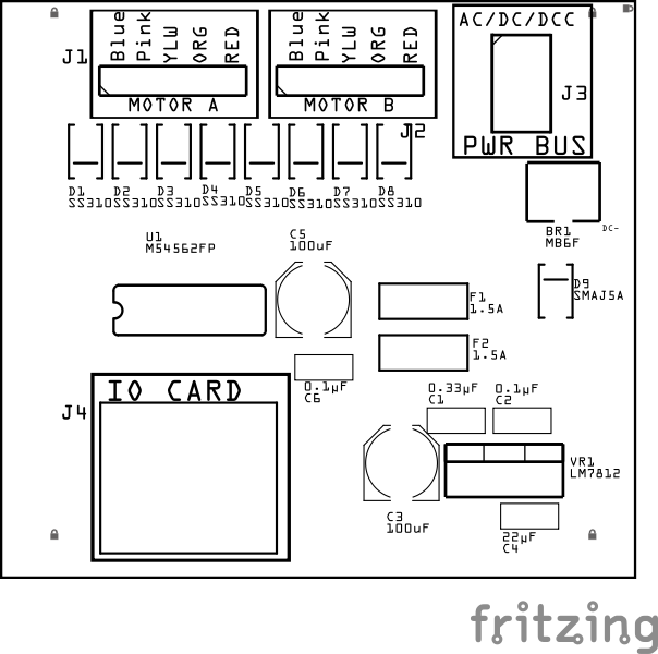
This section combines both the component specifications and the assembly instructions to ensure a smooth assembly process. Below is a comprehensive list of components, their placement on the PCB, and orientation details to assist you during assembly.
High-Level Steps for Assembly:
- PCB for the card can be ordered from any PCB fabricator using these Gerber Files.
- Clean PCB with alcohol to remove residue. See Cleaning_PCB for details.
- See also: Soldering Tips
- PCB Components - listing of components used for PCB assembly
- PCB Parts - listing of parts used for PCB assembly
![]()
![]()
| Component Identifier | Count | Type | Value | Package | Purpose | Orientation |
|---|---|---|---|---|---|---|
| Capacitors | ||||||
| C1 | 1 | Capacitor-Ceramic | 0.33 uF | 1206 X7R | Used by 12 VDC voltage regulator for input filtering. | None |
| C2 | 1 | Capacitor-Ceramic | 0.1 uF | 1206 X7R | Used by 12V voltage regulator for output filtering. | None |
| C3 | 1 | Capacitor-Polymer Solid | 100 µF | 6.3x5.8mm SMD | Used by 12 VDC voltage regulator for input filtering. | Anode is position towards PCB top edge |
| C4 | 1 | Capacitor-Ceramic | 22 uF | 1206 X7R | Used by 12V voltage regulator for output filtering. | None |
| C5 | 1 | Capacitor-Polymer Solid | 100 µF | 6.3x5.8mm SMD | Used to smooth switching of stepper motor driver | Anode is position towards PCB top edge |
| C6 | 1 | Capacitor-Ceramic | 0.1 uF | 1206 X7R | Decoupling for stepper motor driver | None |
| Diodes | ||||||
| D1 - D8 | 8 | Diode | SS310 | 1206 SMD | Protection from flyback current from motor coils | Cathode end has a white line and positioned towards PCB bottom edge |
| D9 | 1 | TVS Diode | SMAJ5A | SMA | GPIO pin Transient Voltage Spike (TVS) protection | Cathode end has a white line and positioned towards PCB top edge |
| Fuses & Protection | ||||||
| F1, F2 | 2 | Fuse-PTC Polymer | JK30, 1.5A, 16 VDC (or more) | 5.1mm pitch, PTH | Protection from current overload from 12 VDC motor | None |
| F3 | 1 | Fuse-PTC Polymer | JK30, 1.5A, 16 VDC (or more) | 5.1mm pitch, PTH | Protects from sustained overcurrent conditions, used by Crowbar diode for when reverse polarity occurs. | None |
| Connectors | ||||||
| J1, J2 | 2 | JST XH Socket | 5P, 2.54mm | - | Connectors to motor | Position so stepper motor plug will align with socket labels |
| J3 | 1 | JST XH Socket or 2-Position Spring Terminal Connector | 2P, 2.54mm | PTH | Connectors to layout accessory bus | Position connector to PCB top edge |
| J4 | 1 | RJ45 Socket | k8P8C | PTH | Network cable (CAT5/6) connection from Digital I/O Card. | Fits only one way |
| ICs | ||||||
| U1 | 1 | IC | M54562FP | SOP20 | Darlington transistor array to amplify low-current signals for stepper motor control | Position IC indent toward PCB left edge |
| Voltage Regulators | ||||||
| VR1 | 1 | Voltage Regulator | L7812CV | PTH | 12 VDC voltage regulator for driving stepper motor(s) | Heat sink towards PC top edge |
Tools Required
Safety Precautions
- See Safety Precautions.
Testing and Verification
Visual Inspection
- Initial Check: Examine the board for any obvious issues like missing components, solder bridges, or components that are misaligned or not fully seated.
- Solder Joint Inspection: Use a magnifying glass or a microscope to inspect solder joints. Look for cold solder joints, insufficient or excessive solder, or any shorts between pads.
Functional Testing
Troubleshooting
- See I2C Trouble Shooting.
Appendences
PCB Specifications
Specifications for the Stepper Motor Driver Breakout Board include:
| Characteristic | Value |
|---|---|
| Max Motors | 2 |
| Output | 12 VDC |
| Max Output1 (per motor) | 1.5A |
| Maximum Number of Stepper Motor Driver Breakout Boards per Digital I/O Card | 2 |
- Max current per motor is based on the LM7812 voltage regulator and fuse.
How It Works
1. ESP32 Control via MCP23017 and AccelStepper Library:
- The ESP32 is responsible for controlling the stepper motors through the MCP23017 GPIO expander using the MCP23017AccelStepper.h library.
- The MCP23017 I/O expander communicates over the I2C bus and handles the GPIO pins needed to control the stepper motors, which allows the ESP32 to control multiple I/O devices with fewer pins.
- The AccelStepper library is great for handling stepper motor movements with smooth acceleration and deceleration. It supports both full-step and half-step modes, which is important for controlling the 28BYJ-48 stepper motors.
2.Digital I/O Card Connected via Network Cable to Stepper Motor Driver Breakout Board:
- The Digital I/O Card connects to the Stepper Motor Driver Breakout Board via a network cable (likely using something like a CAT5 or CAT6 cable for signal routing), which is a good choice for distributing signals over a long distance.
- The Stepper Motor Driver Breakout Board contains the M54562FP, which is responsible for switching the motor phases based on the signals from the MCP23017 GPIO.
3. M54562FP Driving the 28BYJ-48 Stepper Motor:
- The M54562FP is an 8-channel Darlington transistor array, which makes it ideal for controlling the 4 lines needed for each stepper motor (since the 28BYJ-48 stepper motor uses 4 phases).
- The M54562FP is designed to handle the 12 VDC supply that powers the 28BYJ-48 stepper motors. It will sink the current through each of the motor’s windings as needed to drive the motor in the correct sequence.
4. Power Supply (LM7812) for 12 VDC:
- The LM7812 linear voltage regulator provides a regulated 12 VDC output, which is necessary for the M54562FP to drive the 28BYJ-48 stepper motors.
- Since the 28BYJ-48 is a 12 VDC stepper motor, the LM7812 ensures that both the motors and the M54562FP receive the correct voltage, allowing them to operate within their specifications.
5. Supporting Multiple Stepper Motors:
- The design allows the Digital I/O Card to support 2 Stepper Motor Driver Breakout Boards, with each Breakout Board controlling 2 stepper motors.
- Since the M54562FP has 8 channels, each motor will use 4 channels to control its 4 phases. Therefore, each breakout board can support 2 stepper motors using the 8 channels available on the M54562FP.
- The JST XH 5-wire connector on the breakout board makes it convenient to connect the 28BYJ-48 stepper motors without complex wiring.
Overall Design Workflow:
- ESP32 sends commands via I2C to the MCP23017.
- The MCP23017 expands the GPIO pins and outputs the step sequence (using the AccelStepper library) to control the 4 lines of the stepper motors.
- The Stepper Motor Driver Breakout Board, containing the M54562FP, receives these signals and switches the appropriate motor phases by sinking the current through the motor windings.
- The LM7812 regulator supplies a stable 12 VDC to both the M54562FP and the 28BYJ-48 stepper motors, allowing the motors to run reliably.
Connections
Component Designator Connector Label Connector Type Connection Number Description
| Components Designator | Connection Label | Connection Type | Connection Number | Description | Wired To |
|---|---|---|---|---|---|
| J1, J2 | MOTOR A, MOTOR B | JST XH 5P | Pin 1 | Coil A (1st phase) | RJ45 Pin 1 (Motor A) RJ45 Pin 5 (Motor B) |
| J1, J2 | MOTOR A, MOTOR B | JST XH 5P | Pin 2 | Coil B (2nd phase) | RJ45 Pin 2 (Motor A) RJ45 Pin 6 (Motor B) |
| J1, J2 | MOTOR A, MOTOR B | JST XH 5P | Pin 3 | Coil C (3rd phase) | RJ45 Pin 3 (Motor A) RJ45 Pin 7 (Motor B) |
| J1, J2 | MOTOR A, MOTOR B | JST XH 5P | Pin 4 | Coil D (4th phase) | RJ45 Pin 4 (Motor A) RJ45 Pin 8 (Motor B) |
| J1, J2 | MOTOR A, MOTOR B | JST XH 5P | Pin 5 | VCC (Common 12 VDC) | Connected to Vss on M54562FP, powered by ACC BUS |
| J3 | ACC BUS | JST XH 2P, Terminal Connector | Pin 1 | GND | Ground reference for power and signal |
| J3 | ACC BUS | JST XH 2P, Terminal Connector | Pin 2 | +12 VDC (Power Supply) | Powers both the M54562FP and motors |
| J4 | Digital I/O Card | RJ45 Socket | Pin 1 | Motor A (1st phase) | Motor Wire 1 (JST XH Pin 1) |
| J4 | Digital I/O Card | RJ45 Socket | Pin 2 | Motor A (2nd phase) | Motor Wire 2 (JST XH Pin 2) |
| J4 | Digital I/O Card | RJ45 Socket | Pin 3 | Motor A (3rd phase) | Motor Wire 3 (JST XH Pin 3) |
| J4 | Digital I/O Card | RJ45 Socket | Pin 4 | Motor A (4th phase) | Motor Wire 4 (JST XH Pin 4) |
| J4 | Digital I/O Card | RJ45 Socket | Pin 5 | Motor B (1st phase) | Motor Wire 1 (JST XH Pin 1) |
| J4 | Digital I/O Card | RJ45 Socket | Pin 6 | Motor B (2nd phase) | Motor Wire 2 (JST XH Pin 2) |
| J4 | Digital I/O Card | RJ45 Socket | Pin 7 | Motor B (3rd phase) | Motor Wire 3 (JST XH Pin 3) |
| J4 | Digital I/O Card | RJ45 Socket | Pin 8 | Motor B (4th phase) | Motor Wire 4 (JST XH Pin 4) |
PCB Protection
The Stepper Motor Driver Breakout Board includes several key protection mechanisms to safeguard both the board itself and the connected components. Below is a detailed table outlining the protection provided against flyback voltage and reverse voltage, ensuring the longevity and reliability of your setup.
| Protected Component | Location | Protection Component | Function | <div style="text-align: center;">  </div><div style="text-align: left;"> </div><div style="text-align: left;"> |
|---|---|---|---|---|
| Power Bus | Across the input VDC+ and GND power lines | TVS Diode | Provides overvoltage protection to prevent damage from voltage spikes on the accessory bus | Voltage clamp at specified level (e.g., 12 VDC) |
| Stepper Motors | In series with the 12 VDC supply to the motors | Polyfuse or Fuse | Prevents excessive current draw that could damage motors or driver | 1.5A polyfuse (resettable) |
| Stepper Motors | Power input section, supplying 12 VDC to the board | Power Supply (LM7812) | Provides regulated 12 VDC supply to prevent overvoltage to motors and driver | 12 VDC regulated output, 1A or higher current capacity |
| Stepper Motors | Located near the power (before and after LM7812) | Capacitors | Smooths out voltage fluctuations and reduces noise from the power supply | various ceramic and electrolytic capacitors for input and output |
| M54562FP Darlington Array | Internal to te M54562FP Darlington Array | Flyback Diodes (internal) | Protects against voltage spikes (back EMF) from inductive loads such as stepper motors | Integrated into each channel of the M54562FP |
| M54562FP Darlington Array | Across power lines | SS310 Diode-Schottky | Protects against reverse voltage and reverse current. | Reverse Voltage: 40 VDC, Current: 2A. |