SuperMini I/O Status Shield Assembly Guide
Table of contents
Table of contents
Introduction
In conjunction with the LCC Fusion Project Quad-Node Card, the SuperMini I/O Status Shield provides status for the (8) I/O lines. The Shield is typically used initial testing and deployments as a means of verifying whether or not the I/O lines are producing an output or input signal. The Shield used is optional and must be plugged into one of the Quad-Node Card sockets, with a SuperMini ESP32-S3 plugged into the top of the Shield.
flowchart LR;
subgraph layout ["Train Layout"];
  direction LR;
  subgraph quad ["Quad-Node Card"];
	  direction LR;
 	  sm["SuperMini ESP32-S3 (4x)"] --> ss["SuperMini I/O <br/> Shield (4x)"];
  end
end
ss --> device["I/O Devices"];
classDef lSalmonStyle fill:#FFA07A,stroke:#333,stroke-width:2px,font-size:24px;
class bb lSalmonStyle;
classDef lightGrayStyle fill:#d3d3d3,stroke:#333,stroke-width:2px,font-size:24px;
class layout lightGrayStyle;
Assembly and Component Placement
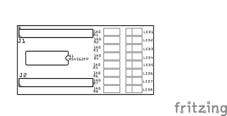
This section combines both the component specifications and the assembly instructions to ensure a smooth assembly process. Below is a comprehensive list of components, their placement on the PCB, and orientation details to assist you during assembly.
High-Level Steps for Assembly:
- PCB for the card can be ordered from any PCB fabricator using these Gerber Files.
- Clean PCB with alcohol to remove residue. See Cleaning_PCB for details.
- See also: Soldering Tips
- PCB Components - listing of components used for PCB assembly
- PCB Parts - listing of parts used for PCB assembly
![]()
![]()
| Component Identifier | Count | Type | Value | Package | Purpose | Orientation |
|---|---|---|---|---|---|---|
| Connectors | ||||||
| J1, J2 | 2 | 9-Pin Female Headers | Long Legged | - | Socket for Super-Mini ESP32-S3 development board(s). Required to allow insertion into the underlying headers. | Position connection outward |
| Resistors | ||||||
| R1-R8 | 8 | Resistor | 1kΩ | 1206 SMD | Current limiting protection for the LEDs. | None |
| Indicators | ||||||
| LED1-LED8 | 8 | LED | Green | 1206 SMD | Status indicator that an I/O line’s state is High when lit. | Reference back of LED, position cathode towards PCB bottom edge |
| Transistors | ||||||
| Q1 | 1 | IC | M54562FP | SOP20 | Darlington transistor array to amplify low-current signals from the (8) ESP32 GPIO pins, enabling driving of LEDs. | Position indent (pin 1) towards PCB right edge |
Tools Required
Safety Precautions
- See Safety Precautions.
Testing and Verification
PCB Configuration
- No configuration required.
Visual Inspection
-
Initial Check: Examine the board for any obvious issues like missing components, solder bridges, or components that are misaligned or not fully seated.
-
Solder Joint Inspection: Use a magnifying glass or a microscope to inspect solder joints. Look for cold solder joints, insufficient or excessive solder, or any shorts between pads.
-
Component Orientation: the IC’s and LED’s are correctly oriented according to the PCB silkscreen or schematic.
Connectivity Testing
- Continuity Check: Use a multimeter in continuity mode to check for continuity between components.
Power-Up Tests
- Install the Shield into the female headers of the Quad-Node Card.
- Install a SuperMini ESP32-S3 module into the female headers of the Shield.
- Install the Quad-Node Card into an LCC Fusion Bus Hub.
- Install a Power-CAN Card in the same bus hub
- Apply Power to the Power-CAN Card.
- Check for Hot Components: Feel for components that are overheating, which could indicate a problem like a short circuit or incorrect component.
Functional Testing
- Using an LCC Configuration Tool
- Configure Event IDs for each of the Node’s input and output lines.
- For output, generate the configured LCC Event ID and verify that the corresponding LED is lite.
- For input, temporarily ground each of the I/O pins and verify that the corresponding LED is lite.
Troubleshooting
- Correct orientation of both the IC and each of the LEDs is the most common issue.
- Verify that the Quad-Node Card is receiving power and that the SuperMini ESP32-S3 module’s LED is lite. If not, check that the LCC Fusion Power-CAN Card is installed in the same Node Bus Hub and powered.
Appendences
PCB Specifications
Specifications for the PCB include:
| Characteristic | |
|---|---|
| Max Input / Output Lines Monitored | 8 |
| Max Input / Output Current (based on M54562FP IC) | 500 mA |
How It Works
The Quad-Node Card monitors the (8) I/O lines of the Quad-Node using a transistor to switch an LED on/off based on the state (High/Low) of the corresponding ESP32 GPIO pin. A current limiting resistor is utilized to protect the LED. The Shield uses the Vcc and GND provided by the Quad-Node Card connection to the LCC Fusion Node Bus Hub.
Design Notes
Implemented as an Arduino Shield (plugs in below ESP32 module);
- Reduces number of wire traces
- Allows for easy additional and removal
- Uses transistor array to:
- reduce components, allowing for fast on/off switching of LED switch based on the input / output line signal levels
- allows higher current levels for the LEDs
- Uses SMD resistors for consistency of SMD uses with other boards (another option would be a 9-pin Resistor Network, which didn’t save space or simplify the wiring).
- LEDs are positioned on PCB’s outer edge for visibility
PCB Protection
The SuperMini I/O Status Shield’s protection is provided by the Quad-Node Card circuit protection.
References
- Super-Mini LED to ESP32-S3 pin assignments.

| SuperMini I/O Status LED | Super-Mini ESP32-S3 Pin |
|---|---|
| LED1 | GP1 |
| LED2 | GP2 |
| LED3 | GP3 |
| LED4 | GP4 |
| LED5 | GP5 |
| LED6 | GP6 |
| LED7 | GP7 |
| LED8 | GP8 |