Test I2C Card Communications
Table of contents
Table of contents
Overview
The many of the LCC Fusion Project cards use an I2C interface for communication to communicate with the LCC Fusion node’s firmware, allowing a LCC Fusion Project’s LCC Fusion Node Cluster to consist of many cards in addition to the LCC Fusion Node Card itself. Each card must have a unique I2C address to avoid conflicts on the I2C bus. Additionally, the thse cards can be set to communicate over either Bus A or Bus B, allowing for flexible layout configurations.
Note: The Node Card firmware supports serial commands (
?,I,T,P) that help with installation and troubleshooting. See: Using the Serial Monitor for Help & Testing.
How To Configure A Card’s I2C Addresses
This guide will walk you through the process of setting the I2C address switches and selecting the bus (Bus A or Bus B) for your LCC Fusion Cards, ensuring proper communication with your LCC Fusion Node(s).
Components
- LCC Fusion Project card (i.e. BOD Card, PWM Card, etc)
COMM ADDRDIP Switches for Address Setting (found on the card)COMM BUS: Bus Selector Jumpers (found on the card)- Small screwdriver or similar tool
Understanding the I2C Address
I2C addresses range in value from 0 to 7. For the card, the address is set using a series of binary switches (DIP switches), located in the COMM ADDR section of the card. The switches are labeled +1, +2, and +4. Each switch can be in one of two positions: ON (1) or OFF (0).
This address is actually an offset that is added to the card’s base address which is unique to the chip is used to support I2C.
Step-by-Step Instructions
-
Locate the DIP Switches:
- Identify the row of DIP switches on your card. These
COMM ADDRswitches are labeled +1, +2 +4.
- Identify the row of DIP switches on your card. These
-
Determine the Desired Address:
- Decide on the I2C address you wish to assign to the card. This will be a value between 0 and 7 (decimal). Ensure this address is unique among all I2C devices on your layout.
-
Setting the I2C Address with DIP Switches
To set the I2C address for the card, use the three DIP switches labeled
+1,+2, and+4. These switches allow you to configure addresses from 0 to 7. The table below shows the DIP switch settings and the resulting I2C address.DIP Switch Settings for Communication Addresses (COMM ADDR)
I2C Communications Address (offset) +1 Switch +2 Switch +4 Switch 0 OFF OFF OFF 1 ON OFF OFF 2 OFF ON OFF 3 ON ON OFF 4 OFF OFF ON 5 ON OFF ON 6 OFF ON ON 7 ON ON ON Explanation:
- +1 Switch: Adds 1 to the address if set to ON.
- +2 Switch: Adds 2 to the address if set to ON.
- +4 Switch: Adds 4 to the address if set to ON.
Example:
If you want to set the communications address to 5:
- +1 Switch: ON (adds 1)
- +2 Switch: OFF
- +4 Switch: ON (adds 4)
Adding these values together gives you 1 + 4 = 5.
-
Set the Bus Selector:
- Locate the bus selector jumper or switch on the LCC Fusion card.
- Set the jumper or switch to the desired bus:
- Bus A: Place the jumper on the pins labeled “Bus A” or move the switch to the “A” position.
- Bus B: Place the jumper on the pins labeled “Bus B” or move the switch to the “B” position.
-
Verify the Settings:
- Double-check the positions of the DIP switches and the bus selector to ensure they match the desired address and bus.
-
Power Cycle the Card:
- After setting the switches and bus selector, power cycle the LCC Fusion card (turn it off and then on) to ensure the new address and bus settings are recognized.
-
Test Communication:
- Use an communications scanner or your LCC system’s diagnostic tools to verify that the card is responding at the newly set address on the correct bus.
Troubleshooting
To ensure the correct operation of cards utilizing I2C communication after assembly, follow the steps below for verification:
-
Adjust the card’s jumper settings for the
COMM BUSto select either Bus A or Bus B, as applicable. -
Set the
COMM ADDRswitches for an address value between 0 and 7.Note that within a LCC Fusion Node Cluster the card addresses (0 - 7) must be unique. Therefore, there 14 possible addresses per cluster available (7 per bus) for a specific card family type.
-
Place the card into a Node Bus Hub, accompanied by a LCC Fusion Node Card.
-
Power up the Node.
 For verification that the LCC Fusion Node Card can communicate via the LCC Fusion Node Bus Hub to the I/O cards via the I2C network, use the Arduino IDE’s Serial Monitor or a Bluetooth Serial Terminal app on your phone to connect to the LCC Fusion Node Card’s ESP32 serial menu.
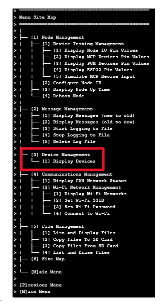
- A visual guide for navigating these settings can be found to the right, illustrating the LCC Fusion Serial Menu Interface. This interface outlines various system configuration procedures, including node setup and address configuration, accessible through a serial connection. This diagram serves as a guide for navigating and understanding system settings.
- Verify the detection of I2C card(s) displaying all attached I/O cards and their network bus settings as follows:
- entering
Mfor theMain Menu - enter
3for[3] Device Management - enter
1for[1] Display Devices
- entering
- Adjust the I/O card’s bus and address settings and then refresh the serial monitor displayto verify that the selections are detected correctly. If not, check the solder connections to the selector’s pins.
If the I2C card is successfully detected, this indicates that the I2C components have been correctly installed and configured. The use of the Arduino IDE or a mobile Bluetooth Serial Terminal app provides flexibility in testing, allowing for convenient and accessible troubleshooting.
- No Response from card:
- Ensure power is correctly supplied to the card.
- Verify the communications address does not conflict with another device.
- Check the DIP switch and bus selector settings again for accuracy.
- Address Conflicts:
- Ensure each device on the communications bus has a unique address.
- Scan the communications bus with a tool to detect existing addresses and avoid duplicates.
By following these steps, you can correctly set the communications address and bus for your card, ensuring smooth operation and communication within your model railroad layout.