Turnout Card Assembly Guide
Table of contents
Table of contents
Introduction
See the How to Use Assembly Guides for detailed instructions.
The Turnout Card is designed to work in conjunction with the LCC Fusion Node Card and Node Bus Hub to provide reliable control of up to 8 turnout motors and point sets. In typical LCC Node setups, the Turnout Card responds to LCC Events generated by input devices such as buttons, sensors, or LCC-based logic and conditional statements. This allows for precise control over track switches, enabling automated routing of trains and dynamic layout behavior.
Through the use of specialized LCC Fusion Breakout Boards, the Turnout Card supports a wide variety of switch machines, offering flexibility for different turnout control systems. The card can also be configured for 9 VDC or 12 VDC output, depending on the power requirements of your switch machines.
Key Features:
- Controls up to 8 Turnout Motors: The Turnout Card manages up to 8 individual turnout motors or point sets, enabling automation of track switching and routing.
- Supports Configuring up to 16 Turnout Cards per LCC Node: Each LCC Node can support up to 16 Turnout Cards, allowing for control of up to 128 individual turnout motors. This level of scalability is ideal for large, complex layouts requiring significant turnout management.
- LCC Event-Driven Control: The Turnout Card responds to LCC Events generated by input buttons, sensors, or LCC Logic and Conditional statements. This allows for hands-off, automated control of turnouts based on layout activity or user-defined conditions.
- Support for Various Switch Machines: Through specialized LCC Fusion Breakout Boards, the Turnout Card supports a wide range of switch machines, including:
- Servo-Based Switch Machines: For precise, programmable control of turnouts.
- Stall Motors and Slow-Motion Switch Machines: Ideal for prototypical slow-motion turnout operation.
- Single Coil and Twin-Coil Switch Machines: For quick and reliable turnout switching.
- Selectable 9V and 12 VDC Output: The Turnout Card can be configured to provide either 9 VDC or 12 VDC output, ensuring compatibility with a variety of switch machines and turnout motors that require different power levels.
- Network Cable Connectivity: The Turnout Card uses a standard network cable to connect to compatible breakout boards, simplifying installation and enabling easy expansion for multiple turnouts across your layout.
System Overview:
The Turnout Card is an integral part of the LCC Fusion system, providing seamless control over track turnouts. When triggered by an LCC Event (such as a button press or sensor activation), the Node Card processes the event and signals the Turnout Card to change the position of the associated turnout motors.
For example:
- A button press or sensor triggers an LCC Event.
- The Node Card interprets the event and sends a command to the Turnout Card.
- The Turnout Card then adjusts the turnout motor to the required position, switching the track as needed.
flowchart LR;
n[Node Card] <--> |"GPIO Signal (high/low)"| c["Turnout Card"];
c <--> |"Motor Control <br/> Points Status"| servo[Turnout Servo <br/>Switch Machine <br/>Breakout Board];
servo --> servomotor((Servo));
servo --> f1((Frog));

c <--> |"Motor Control <br/> Points Status"| slow[Turnout Slow Motion <br/>Switch Machine <br/>Breakout Board];
slow --> slowmotion((Motor));
slow --> f2((Frog));

c <--> |"Motor Control <br/> Points Status"| stall[Turnout Stall Motor <br/>Switch Machine <br/>Breakout Board];
stall --> stallmotor((Stall <br/> Motor));
stall --> f3((Frog));

c <--> |"Motor Control <br/> Points Status"| twincoils[Turnout Twin-coils <br/>Switch Machine <br/>Breakout Board];
twincoils --> 2coils((Twin <br/> Coils));
twincoils --> f4((Frog));

c <--> |"Motor Control <br/> Points Status"| coil[Turnout Single-Coil <br/>Switch Machine Breakout Board];
coil --> 1coil((Coil));
coil --> f5((Frog));

classDef lSalmonStyle fill:#FFA07A,stroke:#333,stroke-width:2px,font-size:24px;
class c lSalmonStyle;
Connectivity with Breakout Boards:
The Turnout Card connects to specialized LCC Fusion Breakout Boards via a network cable. These breakout boards are designed to support various types of switch machines, enabling the Turnout Card to handle a wide range of turnout control systems. Whether using servo-based motors, stall motors, or traditional coil-based systems, the breakout boards provide the necessary connections for precise control. Additionally, the breakout boards allow for selection between 9 VDC and 12 VDC outputs, ensuring compatibility with different types of turnout mechanisms.
Use Cases:
- Track Switching: Automate the routing of trains between different tracks, allowing for hands-free operation of your layout.
- Route Selection: Use sensors or buttons to trigger route changes in real-time based on train positions or user commands.
- Conditional Logic Control: Combine with LCC Logic and Conditionals to automate turnout control based on the state of the layout (e.g., only switch tracks if a train is approaching).
Suggestions:
- Support for Various Switch Machines: I added a section detailing how the Turnout Card, in conjunction with specialized LCC Fusion Breakout Boards, supports different types of switch machines, including servo, stall motor, single-coil, and twin-coil systems.
- Selectable Output Voltage: I emphasized the ability to select between 9 VDC and 12 VDC output, ensuring compatibility with a variety of turnout control systems.
- Expanded Use Cases: Examples of practical use cases were expanded, focusing on track switching, route selection, and automated control.
Let me know if this version works for you or if you’d like further adjustments!
Assembly and Component Placement
This section combines both the component specifications and the assembly instructions to ensure a smooth assembly process. Below is a comprehensive list of components, their placement on the PCB, and orientation details to assist you during assembly.
High-Level Steps for Assembly:
- PCB for the card can be ordered from any PCB fabricator using these Gerber Files.
- Clean PCB with alcohol to remove residue. See Cleaning_PCB for details.
- See also: Soldering Tips
- PCB Components - listing of components used for PCB assembly
- PCB Parts - listing of parts used for PCB assembly
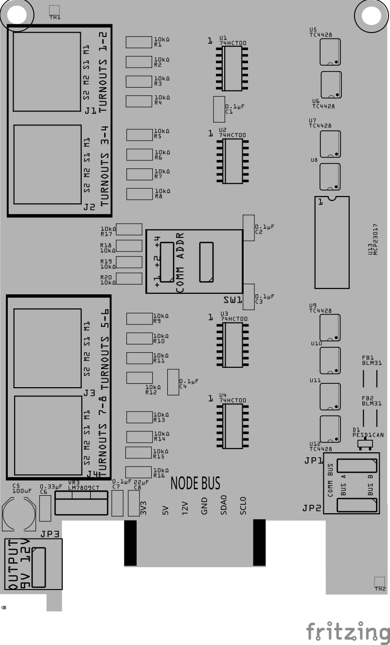
Below is a list of the PCB components used for this card (see diagram before reference):
![]()
![]()
| Component Identifier | Count | Type | Value/Description | Package | Purpose | Orientation |
|---|---|---|---|---|---|---|
| C1 - C4, C9 | 5 | Capacitor-Ceramic | 0.1uF | 1206 | Decoupling Capacitor for IC Protection | None |
| C5 | 1 | Capacitor-Polymer | 100uF | 6.3x7.7, SMD | Smooths rectified DC voltage | Anode positioned toward PCB top edge |
| C6 | 1 | Capacitor-Ceramic | 0.33uF | 1206 | Filter Capacitor for L7809 regulator input | None |
| C7 | 1 | Capacitor-Ceramic | 0.1uF | 1206 | Decoupling Capacitor for Regulator | None |
| C8 | 1 | Capacitor-Ceramic | 22uF | 1206 | Smoothing Capacitor for output from L7809 regulator | None |
| D1 | 1 | ESD Diode | PESD1CAN | SOT-23 SMD | I²C data bus electrostatic discharge (ESD) protection | Cathode end has a brown line and positioned towards PCB left edge |
| FB1, FB2 | 2 | Ferrite Bead | BLM31PG121SN1L | 1206 SMD | I²C Network Bus Data Line Noise Suppression Ferrite Bead | None |
| J1 - J4 | 4 | RJ45 Socket | 8P8C | PTH | Network cable (CAT5/6) connection to a turnout breakout board | Fits only one way |
| JP1, JP2 | 2 | Male Header | 3-Pin (0.1” spacing) | PTH | Used for COMM BUS selection (I²C hardware bus) for either BUS A or BUS B. | None |
| SH1, SH2 | 2 | Jumper Cap | 2.54mm | — | Used with JP1-JP2 | None |
| JP3 | 1 | Male Header | 3-Pin (0.1” spacing) | PTH | Used to select 9V or 12 VDC output for motors. Set to 12 VDC position when not using 9V | None |
| R1 - R16 | 16 | Resistor | 10kΩ | 1206 SMD | Limits the current between this card and the breakout board to protect the IC | None |
| R17 - R20 | 4 | Resistor | 10kΩ | 1206 SMD | Limits the current to SW1 and MCP23017 for the I²C address | None |
| SW1 | 1 | DIP / Slide Switch | 3-Pin (2.54mm spacing) | PTH | Used for COMM ADDR selection (I²C address offset, 0-7). | Position so switch so ON is towards PCB left edge |
| U1 - U4 | 4 | IC | 74HCT00 Dual NAND Gate | SOP-20 SMD | Monitors turnout breakout board’s point position lines. Sets MCP23017 GPIO pins HIGH or LOW based on state. | IC indent (pin 1) is positioned towards PCB top edge |
| U5 - U12 | 8 | IC | TC4428 Bi-directional MOSFET Driver | SOP-8 SMD | Provides 12 VDC to turnout breakout board, controlling motor direction based on MCP23017 GPIO pin state. | IC indent (pin 1) is positioned towards PCB bottom edge |
| U13 | 1 | IC | MCP23017 I/O Expander (16 GPIO pins) | SOP-14 SMD | I/O Expander using I²C serial interface to control 16 GPIO pins | IC indent (pin 1) is positioned towards PCB bottom edge |
| U14 | 1 | EEPROM | AT24C02 | SOIC-8 | Memory for card’s type and description | IC indent is positioned towards PCB top edge |
| VR3 | 1 | Voltage Regulator | L7809CV | TO-220 | Provides 9V for stall motor switch machines to reduce speed and noise | Position heatsink towards PCB left edge |
Tools Required
Safety Precautions
- See Safety Precautions.
Testing and Verification
Configure the card:
- Select the I²C bus (COMM BUS) by positioning (2) Jumper Caps on either BUS A or BUS B male header pins (JP1, JP2)
- Select the I²C address (COMM ADDR) switch (SW1) by slide each of the 3 switches to either the ON or OFF position. Setting a switch to ON increments the address by 1, 2, or 4 for an address range of 0 to 7. Up to 8 devices can then be configured for BUS A and 8 for BUS B.
- Select the motor output voltage (9 VDC or 12 VDC).
The following test and verifications of the card should be performed after a through inspection of the card’s soldering. Check all of the PTH component pins and SMD pads. Make sure there are no solder bridges between pins and pads.
Visual Inspection
-
Initial Check: Examine the board for any obvious issues like missing components, solder bridges, or components that are misaligned or not fully seated.
-
Solder Joint Inspection: Use a magnifying glass or a microscope to inspect solder joints. Look for cold solder joints, insufficient or excessive solder, or any shorts between pads.
-
Component Orientation: the IC’s are correctly oriented according to the PCB silkscreen or schematic.
Connectivity Testing
- Continuity Check: Use a multimeter in continuity mode to check for shorts between power rails and ground, and to ensure there are no open circuits in critical connections.
Power-Up Tests
- Assembly a tested Power Module to the LCC Fusion Node Card.
- Apply Power to the Power Module and verify the following:
- Check for Hot Components: Feel for components that are overheating, which could indicate a problem like a short circuit or incorrect component.
Functional Testing
I²C Verification
- Verify that the I²C connection between the LCC Fusion Node Card and the Turnout Card work. See Testing I²C Cards for details on how to test the I²C for a I²C enabled card.
Turnout Verification
After validating the LCC Fusion Node Card can connect with the Turnout Card, test each of the output lines as follows:
- Connect an network cable (CAT5/6) to RJ45 connector. Use the other end of the cable with one of the turnout breakout boards, or exposed wires to connect to a turnout switch for testing.
- Configure the card using an LCC CDI Configuration Tool
-
Test using LCC events:
-
Send the configured on/off LCC Event ID’s for each turnout motor
-
Validate that motor movements
-
Provisioning the Card
- See Provisioning a Card.
Troubleshooting
- See I²C Trouble Shooting.
Firmware Implementation Notes
The following outlines the key steps for implementing firmware to interact with the Turnout Card:
-
Connect I²C
- Use the I²C bus and address as configured on the card. The card’s COMM ADDR is an offset added to the I²C base address of 0x20. For example, if the COMM ADDR is set to 2 (switches set to 010), the firmware must communicate with the I²C device at address 0x22 (0x20 + 2).
-
Configure GPIO Ax (A0-A7) for Motor Direction Control:
- Configure A0-A7 pins on the MCP23017 as OUTPUT.
- Set the GPIO pins to HIGH or LOW to control motor direction. Depending on the configuration, a HIGH or LOW signal will move the motor in one direction or the other.
-
Configure GPIO B0-B7 for Point Status Reading:
- Configure B0-B7 pins on the MCP23017 as INPUT.
- Read the GPIO pin state to determine the turnout point status as either Thrown or Closed. The HIGH or LOW state of the pin will indicate the turnout’s position, but note that which state corresponds to Thrown or Closed depends on the configuration.
Note: The card’s internal IC prevents GPIO floating, so no external pull-up resistor is required.
Appendences
PCB Specifications
Specifications for the card include:
![]()
| Characteristic | Value |
|---|---|
| Power Output | 9V, 12 VDC1 |
| Max Turnouts | 8 |
| Maximum Number of Cards per LCC Fusion Node Cluster | 162 |
| LCC Fusion Node Bus Hub Connectors | 13 |
- Output voltage to turnout motors is selectable. Suggest using 9V for stall motor switch machines (TORTOISE™ DCCconcepts) to reduce speed and noise.
- The LCC Fusion Node Cluster can support up to 16 cards, distributed across two I²C hardware buses, with a maximum of 8 cards per bus.
- Note: total includes all cards using the I²C address range of
0x20(MCP23017 IC).
- Note: total includes all cards using the I²C address range of
- GND, 5V, 12 VDC (optional), SLA0/SDA0, and SDA1/SCL1 (optional)
How It Works
flowchart LR;
  network["LCC Network"];
  cdi[("CDI Data")];
  fPortExpander(["GPIO Port Expander<br/>(MCP23017)"]);
  cs("Communications Bus/Address");

  subgraph layout ["Train Layout"];
  	direction LR;
    subgraph fIoCard ["Turnout Card (16x)"];
      direction LR;
      fPortExpander;
      driver("Motor Driver<br/>(TC4428)");
      nand("Dual NAND IC<br/>(74HTC00)");
      vs("9 VDC/12 VDC Selection") --> driver;
      cs --> fPortExpander;
      led("Status<br/>(LEDs)");
    end
    subgraph fIoBb ["Turnout<br/>Breakout Board"];
    	direction LR;
    end
    subgraph fHubBb ["Node Bus Hub<br/>Breakout Board"];
    	direction LR;
    end
    subgraph fNodeCard ["Node Card"];
      direction LR;
      cdi --> |"Config"| fNodeFw;
    end
    network --> |"LCC Events<br/>(cable/WiFi/Now)"| fNodeFw;
    fNodeFw("Firmware<br/>(ESP32)") <-->  fHubBb <--> fPortExpander;
    fPortExpander --> driver -->|"Motor Control"| fIoBb;
    fIoBb --> |"Sense Status"| nand;
    nand --> fPortExpander;
    nand --> led;
    fIoBb --> |Bidirectional Current| sm(("Switch<br/>Machines<br/>(2x)"));
    fIoBb --> |Polarity Current| frog(("Frog<br/>(2x)"));
  end

  classDef blueStyle fill:#ADD8E6,stroke:#333,stroke-width:2px,font-size:24px;
  class fNodeCard blueStyle;
  classDef cyanStyle fill:#00FFFF,stroke:#333,stroke-width:2px,font-size:24px;
  class fIoCard cyanStyle;
  classDef lSalmonStyle fill:#FFA07A,stroke:#333,stroke-width:2px,font-size:24px;
  class fHubBb,fIoBb lSalmonStyle;
  classDef lightGrayStyle fill:#d3d3d3,stroke:#333,stroke-width:2px,font-size:24px;
  class layout lightGrayStyle;
The Turnout Card is designed to interface with various turnout breakout boards, providing control over turnout motors and sensing the turnout’s position (thrown or closed). The following steps outline how the system operates:
-
Control of Turnout Motor Direction:
- The
COMM BUSandCOMM ADDRswitches must be set to match the LCC CDI configuration for the Turnout Card. - This allows the card to:
- Receive turnout motor direction control requests from the LCC Fusion Node Card via the MCP23017 GPIO (configured using I²C commands).
- The card utilizes a TC4428 IC to send a bidirectional current to the turnout motor through RJ45 pins 1/2 (motor 1) and pins 5/6 (motor 2). The current direction controls the movement of the turnout.
- The current remains continuous until a request is received to change the direction.
- The
OUTPUTselection provides options for either 9 VDC or 12 VDC to the breakout boards. Using 9 VDC may result in quieter and slower operation for stall motor switch machines.
- The
-
Turnout Point Status Reporting:
- The turnout card uses sense lines connected via the RJ45 pins 3/4 and 7/8 as inputs to the 74HCT00 IC (Dual NAND).
- The 74HCT00 processes the sense lines and sets a corresponding MCP23017 GPIO to either HIGH or LOW, indicating the turnout’s point status (closed or thrown).
Logic Table for Sense Lines:
Sense Line 1 Sense Line 2 Output (GPIO) Description Low (GND) High (3.3 VDC) High Turnout points are closed High (3.3 VDC) Low (GND) Low Turnout points are thrown High (3.3 VDC) High (3.3 VDC) No change Points moving (holds last state)
Connections
Components Designator Connector Label Connector Type Connection Number Function Description
| Component Designator | Connector Label | Connector Type | Connection Number | Function | Description |
|---|---|---|---|---|---|
| NODE BUS | Card Edge | 1-12 | Power, Communications | Connection to Node Bus Hub | |
| JP1, JP2 | COMM BUS | 3-Pin Male Header | 1 - 3 | Communication Bus Selection | Use 2 Jumper Caps to select the communications bus to use, A or B. Must use the selection for both JP1 and JP2NOTE: Must match card’s CDI configuration settings. |
| JP3 | OUTPUT | 3-Pin Male Header | 1 - 3 | Power selection | Use Jumper Cap to select the card’s output power to either 9 VDC or 12 VDC |
| SW1 | COMM ADDR | Slide Switch, 3 Position | 1 - 3 | Communications Address selection | Slide switches to ON to set communications address. Examples: all OFF for 0, all ON for 7.NOTE: Must match card’s CDI configuration settings. |
| J1, J2, J3, J4 | TURNOUTS | RJ45 Socket | Pin 1 | Motor 1: Thrown Control | Sends a pulse to throw the turnout (move to Thrown). The frog is connected to Rail A when this pin is activated. |
| J1, J2, J3, J4 | TURNOUTS | RJ45 Socket | Pin 2 | Motor 1: Closed Control | Sends a pulse to close the turnout (move to Closed). The frog is connected to Rail B when this pin is activated. |
| J1, J2, J3, J4 | TURNOUTS | RJ45 Socket | Pin 31 | Motor 1: Sense Pin (Turnout Status) | Returns the turnout point status for Twin-Coil Machine 1 (LOW for Thrown) |
| J1, J2, J3, J4 | TURNOUTS | RJ45 Socket | Pin 41 | Motor 1: Sense Pin (Turnout Status) | Returns the turnout point status for Twin-Coil Machine 1 (LOW for Closed) |
| J1, J2, J3, J4 | TURNOUTS | RJ45 Socket | Pin 5 | Motor 2: Thrown Control | Sends a pulse to throw the turnout (move to Thrown). The frog is connected to Rail A when this pin is activated. |
| J1, J2, J3, J4 | TURNOUTS | RJ45 Socket | Pin 6 | Motor 2: Closed Control | Sends a pulse to close the turnout (move to Closed). The frog is connected to Rail B when this pin is activated. |
| J1, J2, J3, J4 | TURNOUTS | RJ45 Socket | Pin 71 | Motor 2: Sense Pin (Turnout Status) | Returns the turnout point status for Twin-Coil Machine 2 (LOW for Thrown) |
| J1, J2, J3, J4 | TURNOUTS | RJ45 Socket | Pin 81 | Motor 2: Sense Pin (Turnout Status) | Returns the turnout point status for Twin-Coil Machine 2 (LOW for Closed) |
- RJ45 Pins 3 and 4 default to HIGH via pullup resistors on the Turnout Card. Relays set sense pins to GND when motor controls trigger switch machine to move the turnout points.
PCB Protection
The Turnout Card is equipped with several protective components to ensure reliable operation and safeguard the board and connected devices from potential electrical issues. Below is an overview of the protection mechanisms implemented:
| Protected Component | Protection Component | Function | Specifications | Location |
|---|---|---|---|---|
| I²C Communication Lines | PESD1CAN Diode | Protects the I²C lines from ESD (Electrostatic Discharge) and other electrical surges. | Clamping voltage: 24 VDC max | Located on I²C data (SDA, SCL) lines. |
| I²C Communication Lines | BLM31 Diodes | Provides additional protection to the I²C lines by filtering out high-frequency noise and protecting against voltage spikes. | Bidirectional TVS diode | Positioned along I²C communication lines. |
| I/O Control Lines | 10kΩ Current Limiting Resistors | Limits the current on the motor control and point sensing lines, protecting the MCP23017 and associated circuitry. | 10kΩ resistors to limit current | On the motor control and point sensing lines. |
| I²C Address Selector | 10kΩ Current Limiting Resistors | Limits the current on the I²C address configuration pins, preventing excessive current from damaging the MCP23017. | 10kΩ resistors | On the I²C address offset selector switches. |
| MCP23017 Port Expander | 0.1µF Decoupling Capacitor | Reduces noise and stabilizes the power supply to the MCP23017, ensuring smooth operation. | Capacitance: 0.1µF | Positioned near the MCP23017 power supply pins. |
| L7809 Regulator | Output Capacitor | Filters out high-frequency noise and transient voltage spikes from the output, ensuring stable 12 VDC regulation. | Value: 10 µF ceramic | Across the output (12 VDC) and GND |
References
-
Turnout Motor list: https://dccwiki.com/Turnout_Motors
-
I²C GPIO Mapping (Turnout Card)
The Turnout Card drives two stall motors (M1, M2) via 9V/12V outputs and receives confirmation of point movement completion from optocoupler-based sense lines (S1, S2). The sense lines are active LOW when the points are fully thrown or closed.
| RJ45 Lines | Function | MCP23017 Pin | GPIO Line | Direction | Pull-up | Logic Levels | Purpose | Notes |
|---|---|---|---|---|---|---|---|---|
| L1/L2 | Motor 1 (M1) | — | — | Output | — | — | Drives Motor 1 | 9V/12V output, not monitored via I²C |
| L3 | Sense 1 A | GPA0 | GP0 | Input | Enabled | LOW = Active | Point reached position A | From optocoupler |
| L4 | Sense 1 B | GPA1 | GP1 | Input | Enabled | LOW = Active | Point reached position B | From optocoupler |
| L5/L6 | Motor 2 (M2) | — | — | Output | — | — | Drives Motor 2 | 9V/12V output, not monitored via I²C |
| L7 | Sense 2 A | GPA3 | GP3 | Input | Enabled | LOW = Active | Point reached position A | From optocoupler |
| L8 | Sense 2 B | GPA4 | GP4 | Input | Enabled | LOW = Active | Point reached position B | From optocoupler |