Turnout Coil Switch Machine Breakout Board Assembly Guide
Table of contents
Table of contents
Introduction
The Turnout Coil Switch Machine Breakout Board, used in conjunction with the LCC LCC Fusion Node Card, Turnout Card, and a coil switch machine, provides both motor control and turnout point position sensing, while also handling frog polarity switching. The board leverages a set of transistors to reliably switch the frog connection between Rail A and Rail B, based on the turnout’s position, ensuring proper electrical connection as the turnout moves between the Thrown and Closed positions.
By interfacing directly with the Turnout Card, this breakout board provides a seamless way to control the turnout motor direction and manage frog polarity automatically, making it ideal for complex layout control and automation.
This board contains a Capacitor Discharge Unit (CDU) to drive the coil switch machines using solenoid coils to move the points. The CDU can be charged directly from the Turnout Card. Connection to the PWR BUS is optional.
Application Design Diagram
flowchart LR;
can["CAN Network"];
subgraph layout ["Train Layout"];
n["Node Card"];
nb["Node Bus Hub"];
c["Turnout Card"];
bb[Turnout Coil <br/> Switch Machine <br/> Breakout Board];
frog1["Frog 1"];
frog2["Frog 2"];
direction LR;
smotor1["Single-Coil, or<br/>Twin-Coils"];
smotor2["Single-Coil, or<br/>Twin-Coils"];

onodes["Other LCC Nodes"] <-->  |"Event ID"| can;
can <-->  |"Event ID"| n;
subgraph cluster ["LCC Fusion Node Cluster"];
n <---> |"GPIO Signal <br/> (high/low)"| nb;
nb <--> |"Commuications <br/>Power"| c;
end;
c <--> |"Turnout Control <br/> (12 VDC, direction, status)"| bb;

bb --> |"DC Power <br/>(150 ms on / off)"| smotor1;
bb --> |"Track Power <br> (Rail A/B)"| frog1;
bb --> |"DC Power <br/>(150 ms on / off)"| smotor2;
bb --> |"Track Power <br> (Rail A/B)"| frog2;
pbus["PWR BUS"] --> |"AC/DC/DCC"|bb;
tbus["TRACK BUS"] --> |"AC/DC/DCC"| bb;
end;
classDef lSalmonStyle fill:#FFA07A,stroke:#333,stroke-width:2px,font-size:24px;
class bb lSalmonStyle;
classDef lightGrayStyle fill:#d3d3d3,stroke:#333,stroke-width:2px,font-size:36px;
class layout lightGrayStyle;
Usage
This breakout board is for use with both 2-wire switch machines using one solenoid (single coil) and 3-wire switch machines using two solenoids (twin-coils).
| Manufacturer | Product | Switch Machine Type | Breakout Board to Switch Machine Connects | Frog Polarity | Points Status1 | Comments |
|---|---|---|---|---|---|---|
| KATO | Unitrack Turnout | Single-Coil | Connect 1 to red wireConnect 2 to black wire |
Breakout Board | Breakout Board | Configure Turnout Card for 12 VDC DC Motor Output |
| Rapido | Rapido RailCrew Switch Machine | Single-Coil | Connect 1 to red wireConnect 2 to black wire |
Breakout Board | Breakout Board | Configure Turnout Card for 12 VDC DC Motor Output |
| Atlas | Snap Switch Machines | Twin-Coils | Connect 1 to left connectorConnect COM to middle connectorConnect 2 to right connector |
Breakout Board | Breakout Board | |
| Hornby | R8014 Point Motor R8243 Surface Mount Point Motor |
Twin-Coils | Connect 1 to Red wireConnect COM to Black wireConnect 2 to Green wire |
Breakout Board | Breakout Board | Configure Turnout Card for12 VDC DC Motor Output. R8014 Wiring (PDF) R8243 Wring (PDF) |
| Model Railroad Control Systems (MRCS) | MP1, MP1 (v2), MP5 | Twin-Coils | Connect 1 to poz1 connectorConnect COM to COM connectorConnect 2 to poz2 connector |
Breakout Board, or MRCS MP1, MP5 |
Breakout Board | MP1 Wiring (PDF) MP5 Wiring (PDF) For MP4 & MP10, use Turnout Slow Motion Switch Machine Breakout Board |
| Peco | TwistLock Motor (PL-1000, PL-1000E Turnout Motor PL-10/PL-10E Pico Side Mount |
Twin-Coils | Connect 1 to Black or Red wireConnect COM to both Green wiresConnect 2 to other Black or Red wire |
Breakout Board, or Peco Turnout Motor (PL10) |
Breakout Board | PL10 Wiring (PDF) Switch 1 and 2 connections to reverse motor |
| Rails Connect (by DCCconcepts) | Rails Connect Point Motors RPM-SM.1, RPM-UB.1 | Twin-Coils | Connect 1 to Red wireConnect COM to Green wireConnect 2 to Black wire |
Breakout Board | Breakout Board |
- To produce LCC Events, the breakout board is must be used since the switch machine itself is not integrated with LCC.
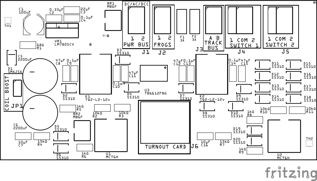
Assembly and Component Placement
This section combines both the component specifications and the assembly instructions to ensure a smooth assembly process. Below is a comprehensive list of components, their placement on the PCB, and orientation details to assist you during assembly.
High-Level Steps for Assembly:
-
PCB for the card can be ordered from any PCB fabricator using these Gerber Files.
-
Clean PCB with alcohol to remove residue. See Cleaning_PCB for details.
-
See also: Soldering Tips
-
PCB Components - listing of components used for PCB assembly
-
PCB Parts - listing of parts used for PCB assembly

| Component Identifier | Count | Type | Value | Package | Purpose | Orientation |
|---|---|---|---|---|---|---|
| Capacitors | ||||||
| C1 | 1 | Capacitor-Polymer | 100 uF | 6.3x5.8mm SMD | Smooths rectified DC voltage | See silk screen image |
| C2 | 1 | Capacitor-Ceramic | 0.33 uF | 1206 X7R | Smooth input for voltage regulator | None |
| C3 | 1 | Capacitor-Ceramic | 22 uF | 1206 X7R | Smooth output for voltage regulator | None |
| C4 | 1 | Capacitor-Ceramic | 0.1 uF | 1206 X7R | Smooth output of voltage regulator | None |
| C5, C6 | 2 | Aluminum Capacitor | 2200 uF | 13mm | Provides current to drive coil switch coils | Position anode towards PCB right edge |
| C7, C16 | 2 | Capacitor-Ceramic | 10 uF | 1206 X7R | Part of the 150 ms pulse timing circuit (RC) to control discharge rate | None |
| C8, C11, C12, C15 | 4 | Capacitor-Ceramic | 47uF | 1206 X7R | Use to handle bulk energy for the relay coil’s inrush | None |
| C9, C10, C13, C14 | 4 | Capacitor-Ceramic | 0.1uF | 1206 X7R | Use of relay coil high-frequency snubbing | None |
| Diodes | ||||||
| BR1, BR2 | 2 | Bridge Rectifier | MB6F | SMD | Converts DCC/AC to DC | Position indent to PCB left edge (pin1 DC-) |
| D1 | 1 | TVS Diode | SMAJ5A | SMA | GPIO pin Transient Voltage Spike (TVS) protection | Cathode end has a white line and positioned towards PCB top edge |
| D2, D4, D7, D9 | 4 | Diode | SS310 | SMD | Flyback for relay coils | Cathode end has a white line and positioned towards PCB left edge |
| D3, D10 | 2 | Diode | SS310 | SMD | A negative-clamp, preventing the PWM input from swinging more than 0.6 VDC below GND and thus ensuring clean, well-defined PWM edges | Cathode end has a white line and positioned towards PCB left edge |
| D5, D6, D19, D20 | 4 | Diode | SS310 | SMD | Reverse current protection for RC circuit | Cathode end has a white line and positioned towards PCB left edge |
| D8, D9 | 2 | Diode | SS210 | SMD | Reverse current protection from motor driver output to relay coil (-) | Cathode end has a white line and positioned towards PCB left edge |
| D11-D18 | 8 | Diode | SS310 | SMD | Flyback for switch machine coils | Cathode end has a white line and positioned towards PCB left edge |
| Fuses & Protection | ||||||
| F1, F2 | 2 | Fuse-PTC Polymer | JK30, 1.5A, 16 VDC (or more) | 5.1mm, PTH | Current overload protection from track (frog) | None |
| Connectors | ||||||
| J1 | 1 | JST XH Socket | 2P, 2.54mm | PTH or Spring Terminal | Connector to PWR BUS (V+, GND) for charging 2200uF capacitor and regulator for TB6612FNG IC motor driver | Position connection towards PCB top edge |
| J2 | 1 | JST XH Socket | 2P, 2.54mm | PTH or Spring Terminal | Connector to turnout frog | Position connection towards PCB top edge |
| J3 | 1 | JST XH Socket | 2P, 2.54mm | PTH or Spring Terminal | Connector to track bus power rails (Rail A and Rail B) | |
| J4, J5 | 2 | JST XH Socket | 2P, 2.54mm | PTH or Spring Terminal | Connector to switch machines (coils) | Position connection towards PCB top edge |
| J6 | 1 | RJ45 Socket | 8P8C | PTH | Network cable (CAT5/6) connection from Digital I/O Card | Fits only one way |
| Selectors | ||||||
| JP1 | 1 | Male Header | 2P, 2.54mm | n/a | Use Jumper Cap to boost power to the coils by using (2) 2200uF capacitors. | None |
| SH1 | 1 | Jumper Cap (Shunt) | 2.54mm | - | Use with JP1 | None |
| Resistors | ||||||
| R1 | 1 | Resistor | 68Ω | 1206 SMD | Limits current to capacitor for 1 sec charge time | None |
| R2, R3, R10, R11 | 4 | Resistor | 10kΩ | 1206 SMD | Pullups for Optocoupler LED Anode | None |
| R4, R7 | 2 | Resistor | 15kΩ | 1206 SMD | Part of the 150 ms pulse timing circuit (RC) to control discharge rate | None |
| R5, R6, R8, R9 | 2 | Resistor | 1kΩ | 1206 SMD | current limiting to Optocoupler LED Anode | None |
| ICs | ||||||
| U1, U2 | 2 | Optocoupler | MCT6H | DIP8, PTH | Convert RJ45 bipolar control signal into lower power signals to Motor Drivers (U1, U2) | Position IC’s indent towards PCB top edge |
| U3 | 1 | Motor Driver | TB6612FNG | SSOP-24 | Drives coil(s) with pulse bipolar | Position IC’s dimple/dot towards PCB top/right edges |
| Voltage Regulators | ||||||
| VR1 | 1 | Voltage Regulator | LM7805CV | TO-220, SMD | Provides 5V to relays, 2200uF, optocoupler, and Drive Motor (U1, U2) | Position heat sink towards PCB top edge |
| RELAY | ||||||
| K1, K2 | 2 | Relay DPDT | TQ2-L2-12V | TQ2, DIP-10 | Switches Track A/B to Frogs | Indent (black line) towards PCB top edge |
Tools Required
Safety Precautions
- See Safety Precautions.
Testing and Verification
Visual Inspection
- Initial Check: Examine the board for any obvious issues like missing components, solder bridges, or components that are misaligned or not fully seated.
- Solder Joint Inspection: Use a magnifying glass or a microscope to inspect solder joints. Look for cold solder joints, insufficient or excessive solder, or any shorts between pads.
Functional Testing
-
Connect accessory bus to
PWR BUSconnector (J1) -
Connect track bus rails to
TRACK BUSconnector (J3) -
Test Motor 1
-
Connect a single or twin coil switch machine to
MOTOR 1(J4) -
Momentarily connect 12 VDC+ (e.g. accessory bus) to RJ45 socket (J5) pin 1 and GND to pin 2.
Access RJ45 pins from PCB bottom). Pin 1 has a square solder pad. Pin 2 is position above it, with other pins alternating between the rows.
-
Results:
- one of the motor’s coils moves the turnout points in one direction.
-
-
Check for movement by the 2nd turnout coil by momentarily touching 12 VDC+ to pin 2 and GND to pin 1.
Troubleshooting
Appendices
PCB Specifications
Specifications for the Turnout Coil Motion Switch Machine Breakout Board include:
| Characteristic | Value |
|---|---|
| Input (Layout’s power bus or dedicated supply) | 12VDC-35 VDC AC, DC, or DCC |
| Max Coil Switch Machines (per Breakout Board) | 2 |
| Max Coil Switch Machines (per LCC Node Cluster) | 8 (per 1 sec of charging)1 |
| Max Input Current (CDU charging) | 12 VDC @ 180 mA for 1 sec |
| Max Output (to each Coil) | Up to 25 VDC @ 150 ms per 2200 µF2,4 |
| Max Output (Track Bus to Frog) | 2.5 A3 |
-
The default 12 VDC used for 1-second CDU charging is supplied via the Turnout Card. The LCC Node Cluster provides 12 VDC @ 1.5A, supporting up to 8 breakout boards charging simultaneously. Optionally, the user may offload this power by connecting an external power supply or layout-wide power bus (PWR BUS).
-
Coil resistance varies by manufacturer. Some switch machines may not operate reliably with a single 2200 µF capacitor. If this occurs, install the jumper (JP1) to connect a second 2200 µF capacitor, effectively doubling the pulse energy.
-
Output current to the frog from the Track Bus is limited by the PCB trace width of 48 mil (typically supports ~2.5 A with 1 oz copper).
-
If the switch machine stalls or the throw is insufficient, consider increasing the capacitor value in the RC timing circuit (keep all four capacitors the same value).
Pulse Time (τ = R × C) Resistors (R10,R11,R14,R15) Capacitors (C6-C9) 150 ms (0.15s) 15kΩ 10uF 30 ms (0.3s) 15kΩ 22uF 500 ms (0.5s) 15kΩ 33uF
How It Works
The Turnout - Coil Switch Machine Breakout Board is designed to control both single-coil and twin-coil switch machines using a flexible, pulse-based drive system. It integrates seamlessly with the LCC system via the Turnout Card, supports AC, DC, or DCC input, and uses a motor driver IC to manage turnout movement. The board also includes configurable energy output and sensing support for turnout position feedback, with frog polarity now handled by a TQ2-L2-12V dual-coil latching relay.
Power Supply and Conditioning:
- The primary source of power is the Turnout Card. The bipolar 12 V is rectified using a bridge rectifier to provide a stable DC 12 V supply.
- Note that the board optionally supports receiving AC, DC, or DCC power through the PWR BUS, which is rectified using a bridge rectifier to provide a stable DC supply. This will override the use of power from the Turnout Card.
- A 5 V regulator (e.g., LM7805) supplies power to the TB6612FNG motor driver and logic components.
- A 2200 µF capacitor is charged through a 68 Ω resistor to store energy for driving the turnout coil.
- A jumper (JP1) allows the user to connect a second 2200 µF capacitor, increasing energy to 4400 µF for larger switch machines.
Input and Direction Control:
- Directional signals arrive from the Turnout Card via RJ45 Pins 1 and 2 for switch 1 (pins 5/6 for switch 2), carrying polarity-based control for turnout direction.
- These signals are isolated and converted using a dual optocoupler (MCT6H), producing OC1 and OC2 outputs.
- Each optocoupler’s output connects to both:
- The AIN1/AIN2 direction for switch 1 (BIN1/BIN2 for switch 2) inputs of the TB6612FNG motor driver
- An RC timing circuit (10 µF + 15 kΩ + SS310 diode) that generates a ~150 ms pulse to the PWMA for switch 1 (PWMB for switch 2) input
- Pullups (10k) when OC1/OC2 are off so they are not floating (TB6612FNG has no internal pullups)
Coil Pulse via Motor Driver:
Note: A TB6612 motor driver instead of discrete MOSFETs because it provides reliable polarity control for dual-coil latching relays in a compact form factor with fewer components.
- The TB6612FNG receives:
- Direction from AIN1/AIN2 and BIN1/BIN2 (via the 2 optocouplers)
- Pulse from RC circuit (to PWMA/PWMB)
- Motor power from VM1 (connected to the charged capacitor)
- When triggered, the TB6612FNG outputs a 150 ms burst across AO1 and AO2, delivering power to the turnout coil(s).
- For twin-coil switch machines, the COM terminal is connected to GND, and the output pulse is applied to Coil 1 or Coil 2 based on direction.
Flyback Protection:
- Four SS310 Schottky diodes are used across the coil terminals (1/COM and 2/COM) to suppress voltage spikes when the coils deactivate, protecting the motor driver.
Frog Polarity Switching (via TQ2-L2-12V Relay):
-
The board employs a TQ2-L2-12V dual-coil latching relay to control the polarity of the frog. One coil is dedicated to setting the relay, while the other is used to reset it.
- Each relay coil is driven directly by the motor driver’s output using a 150 ms pulse. The two coils are wired in opposite directions, so a change in the motor driver’s output polarity selectively energizes either the set or reset coil.
- This approach ensures reliable, momentary actuation without requiring continuous power, which could lead to overheating or damage in a latching relay. Since latching relays are designed to hold their state mechanically, continuous current is unnecessary and potentially harmful.
- The TQ2-L2-12V relay reliably toggles the frog connection between Track Bus A and Track Bus B, ensuring the frog always matches the polarity of the selected route.
Turnout Point Sensing:
- The optocoupler outputs (OC1/OC2) also pull the RJ45 sense lines Pins 3/4 for Switch 1 and Pins 7/8 for Switch 2 low depending on direction.
- This allows the Turnout Card to determine if the switch is in the thrown or closed position.
The board is compatible with both 1-coil and 2-coil switch machines, with no jumper required. Users simply wire their switch machine using 2 or 3 terminals depending on the design. The board is engineered for ease of use, protection, and reliable turnout control using a mix of analog and digital logic.
<img src=”/LccFusionProject/assets/images/pcbs/Breakout_Boards/Turnout_Coil_Switch_Timing.png/” style=”zoom:30%; float:center” /
Timing and Pulse Generation Explanation
The diagram above illustrates how the Turnout - Coil Switch Machine Breakout Board uses a shared RC timing circuit to convert a directional polarity signal (via OC1/OC2) into a brief, high-current pulse for the motor driver input (PWMA). Here’s a breakdown of what’s happening across each transition:
-
Key Components Involved
-
MCT6H Optocoupler (OC1/OC2):
- Detects the polarity of the control signal from the Turnout Card.
- Only one channel is HIGH at any time, based on current flow direction.
-
Acts as both a signal isolator and a logic switch.
- Series Diodes (D1, D2):
- One diode is inline between each optocoupler output and the shared RC timing circuit.
- Prevents back feeding between OC1 and OC2, ensuring isolated triggering.
- RC Timing Circuit (R + C):
- A resistor (e.g., 15kΩ) and ceramic capacitor (e.g., 10µF X7R) form a charge circuit.
- When OCx goes HIGH, the capacitor begins to charge, creating a voltage ramp.
- This rising voltage is seen at the PWMA pin of the TB6612FNG.
- PWMA Input (Motor Driver):
- Recognizes a HIGH signal (typically >2V) to enable the motor channel for a pulse.
- As the capacitor voltage drops below ~0.8V, PWMA returns LOW.
- This delivers a single ~150 ms burst to the motor coil, preventing overheating.
-
Discharge Diode (D3):
- Connected from PWMA to GND (cathode to PWMA).
- Ensures the capacitor can discharge cleanly after each pulse, resetting the circuit.
- Connected from PWMA to GND (cathode to PWMA).
-
-
Pulse Cycle
- Turnout is Thrown (OC1 HIGH):
- OC1 goes HIGH
- Capacitor begins charging through R
- PWMA crosses HIGH threshold → motor pulse starts
- After ~150 ms, capacitor is fully charged, PWMA falls to LOW causing motor driver to turn off current to turnout coil
- Turnout Holds Position:
- OC1 remains HIGH
- Capacitor remains charged (no further current flow)
- PWMA remains LOW (motor driver off)
- Coil is safe from prolonged current
- Turnout is Closed (OC2 HIGH):
- OC1 goes LOW, OC2 goes HIGH
- Same process repeats through D → R → C
- PWMA sees new 150 ms pulse → motor actuates in other direction
- Turnout is Thrown (OC1 HIGH):
** Benefits of This Approach**
- No firmware timing required
- Safe, non-latching control of coil motors
- Only one pulse per change, regardless of signal duration
- Universal compatibility with most single- and twin-coil switch machines
PCB Protection
| Protected Component | Protection Component | Function | Specifications | Location |
|---|---|---|---|---|
| Turnout Card (MCP23017 GPIOs) | MCT6H Optocoupler | Electrically isolates control signals from high-current switching, preventing back-EMF and voltage spikes from reaching the Turnout Card. | - Isolation Voltage: 5300 VDC RMS - Forward Current: 10 mA - Output Type: Open-Collector |
Between RJ45 input control signals and Relay |
| 5 VDC Regulator & Power Supply | Bridge Rectifier | Ensures correct polarity, allowing AC, DC, or DCC power sources while preventing reverse polarity damage. | - Maximum Input Voltage: 600 VDC AC - Forward Current: 0.5A (Max 1A surge) - Forward Voltage Drop: 1.1 VDC per diode - Reverse Leakage Current: 5µA (at 600 VDC) |
Between external power input and 5V regulator |
| Accessory Power (ACC VDC+) | TVS Diode | Provides overvoltage protection to prevent damage from voltage spikes on the accessory bus | Voltage clamp at specified level (e.g., 12 VDC) | Across the ACC VDC+ and ACC GND power lines |
| Track Power | PPTC Polyfuse | Protects from sustained overcurrent conditions by increasing resistance. Resets once the fault condition is cleared. | Fuse Rating: Based on max track current (typically 0.5-3.5A depending on track power). | In series with the track power supply, between the power source and the track. |
| Coil Motors | Flyback Diode | Protects the circuit from high-voltage spikes caused by inductive loads (switch machine coils) when switching off. | Diode Type: Schottky Max Current: Min 2A Reverse Voltage: Min 25 VDC |
Across the turnout switch machine coils. |
| LM7805CV Regulator | Capacitors (Input/Output) | Stabilizes voltage and reduces noise on the input and output of the voltage regulator. | Input Cap: 470uF, 0.33µF Output Cap: 0.1µF | Input cap across the input pin and GND. Output cap across the output pin and GND. |
| DCC and ACC Circuits | Separate Ground Planes | Isolates DCC and accessory grounds to prevent interference | N/A | Between DCC and ACC |
Connections
The purpose of the Turnout Twin Coils Switch Machine Breakout Board and its connectors is to facilitate quick and easy connections between the Turnout Card and a turnout controlled by twin-coils (i.e. snap switches)
| Component Designator | **Connector Label ** | Connector Type | Connection Number | Description |
|---|---|---|---|---|
| J1 | PWR BUS | JST XH, Spring Terminal | 1, 2 | AC/DC connection to the layouts accessory bus or dedicated power supply (not to DCC) |
| J2 | FROGS | JST XH, Spring Terminal | 1, 2 | Connection to power turnout frogs |
| J3 | TRACK BUS | JST XH, Spring Terminal | A, B | Connections to the layout track bus for Rail A and Rail B. Used to power the frog when. If necessary, switch the connections to match the frog to the correct rail. |
| J4, J5 | MOTOR 1 / MOTOR 2 | JST XH, Spring Terminal | 1, 2 | Connection to 1 or 2 twin-coils switch machines. Connections 1 and 2 are for one side of each coil. COM is for the shared connection of the 2 coils. |
| J6 | TURNOUT CARD | RJ45 Socket | 1 - 8 | Refer to Turnout Card’s connection table for the function of each pin |
| JP1 | COIL BOOST | JUMPER | n/a | Use Jumper Cap to boost power to the coils by using (2) 2200uF capacitors. |
References
- Preparing a PCB for Soldering
- Solder Tips
- Turnout Motor list: https://dccwiki.com/Turnout_Motors