Turnout Servo Switch Machine Breakout Board Assembly Guide
[TOC]
Introduction
The Turnout Servo Switch Machine Breakout Board, used in conjunction with the LCC LCC Fusion Node Card, Turnout Card, and a servo stall motor based switch machine, provides PWM based servo motor control and turnout point position sensing, while also handling frog polarity switching. The board leverages dual mechanical relays to reliably switch the frog between Rail A and Rail B, based on the turnout’s position. Each relay is responsible for controlling one frog, ensuring proper electrical connection as the turnout moves between the Thrown and Closed positions.
[!IMPORTANT]
Requires a PWM based 5V 3-wires servo (i.e. SG90).
To accommodate various turnout and configuration, servo movement is configuable in increments of 15° (15°, 30°, 45°, 90°) based on installation of a resistor.
By interfacing directly with the Turnout Card, this breakout board provides a seamless way to control the turnout motor direction and manage frog polarity automatically, making it ideal for complex layout control and automation.
Usage:
This breakout board is for use with 3-wire servo used as a stall motor switch machines. Wiring examples:
| Manufacturer | Product | Breakout Board to Switch Machine Connects | Comments |
|---|---|---|---|
| SG90 9g | Connect S to Yellow wireConnect V+ to Red wireConnect G to Black wire |
Servo comes with a standard JST XH 3P plug to plug into the breakout board JST XH socket |
flowchart LR;
can["CAN Network"];
subgraph layout ["Train Layout"];
direction LR;
n["Node Card"];
c["Turnout Card"];

can <--> |"LCC Event <br/> (on/off/speed"| n;
n <--> |"GPIO Signal <br/> (high/low)"| c;
c <--> |"Motor Control <br/> (direction)"| bb[Turnout <br/> Servo Switch Machine<br/> Breakout Board];
bb --> |"PWM Signal <br/>(5 VDC, position)"| m("Servo Motor <br/> (2x)");
bb --> |"Frog Power<br/> (Rail A/B)"| frog["Frog (2x)"];
tbus["TRACK BUS"] --> bb;
abus["ACC POWER"] --> bb;
end;

classDef lSalmonStyle fill:#FFA07A,stroke:#333,stroke-width:2px,font-size:24px;
class bb lSalmonStyle;
classDef lightGrayStyle fill:#d3d3d3,stroke:#333,stroke-width:2px,font-size:24px;
class layout lightGrayStyle;
Assembly-Configuration Options
The Turnout Servo Switch Machine Breakout Board supports multiple assembly configurations to fit various use cases.
| Configuration | Required/Optional | Description | Required Components | Optional Components |
|---|---|---|---|---|
| Turnout Card | Required | Connection to Turnout Card for 12v bipolar inputs and point set position outputs | Turnout Card Connector (J6) | |
| Power via PWR BUS | Optional | Allows board to be powered from layout accessory bus (AC, DC, or DCC) | • Connector (J1) • Bridge Rectifier (BR1) • 5V Regulator (VR1) • Filter Capacitors (C2, C3, C4) |
TVS Diode (D1) |
| Power via Turnout Card | Optional | Allows board to be powered from Turnout Card (via LCC Node Bus, LCC Node) | • Bridge Rectifier (BR2) • 5V Regulator (U2) • Filter Capacitors (C2, C3, C4) |
TVS Diode (D1) |
| Primary Servo Output | Required | Generates PWM control signal for a single turnout servo | • NE556 Timer (U1) • Servo 1 Connector (J4) • 50Hz and Timing: Resistors (R1, R2, R9-R11, Capacitor (C1, C5, C7), Diodes (D5, D6) • Optocoupler: (C6, U2, D3, D4, R12, R13) |
— |
| Second Servo Support | Optional | Adds support for controlling a second servo using the same timing pulses | NE556 Timer (U1, R14, R15, R20-R22, C8, C9, C10) • Servo 2 Connector (J5) • Optocoupler: (C11, U3, D8, D9, R23, R24) |
— |
| Primary Servo Frog Polarity Switching | Optional | Switches frog connection between Track Bus A/B using latching relay | • Dual-Coil Latching Relay (K1) • Motor Driver (U5, R3-R5) • Frog Connector (J2) • Track Bus Connector (F1, F2, J3) |
— |
| Secondary Servo Frog Polarity Switching | Optional | Switches frog connection between Track Bus A/B using latching relay | • Dual-Coil Latching Relay (K2) • Motor Driver (U5, R6-R8) • Frog Connector (J2) • Track Bus Connector (F1, F2, J3) |
— |
| Turnout Position Indicators (LEDs) | Optional | Provides visual indication of turnout state based on OC1/OC2 opto output | • Indicators (LED1 - LED4) • Current-Limiting Resistors (R16 - R19) |
— |
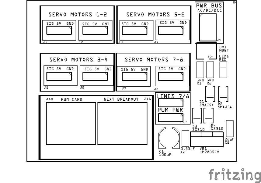
Assembly and Component Placement
This section combines both the component specifications and the assembly instructions to ensure a smooth assembly process. Below is a comprehensive list of components, their placement on the PCB, and orientation details to assist you during assembly.
High-Level Steps for Assembly:
-
PCB for the card can be ordered from any PCB fabricator using these Gerber Files.
-
Clean PCB with alcohol to remove residue. See Cleaning_PCB for details.
-
See also: Soldering Tips
-
PCB Components - listing of components used for PCB assembly
-
PCB Parts - listing of parts used for PCB assembly
![]()
![]()
| Component Identifier | Count | Type | Value | Package | Purpose | Orientation |
|---|---|---|---|---|---|---|
| Capacitors | ||||||
| C1 | 1 | Capacitor-Polymer | 100 uF | 6.3x5.8mm SMD | Smooths rectified DC voltage | See silk screen image |
| C2 | 1 | Capacitor-Ceramic | 22 uF | 1206 X7R | Used by 5V voltage regulator for output filtering. | None |
| C3, C20 | 2 | Capacitor-Ceramic | 1µF | 1206 X7R | Pullup for Timing Circuit for PWM 50Hz (period / duty cycle) | None |
| C4, C19 | 2 | Capacitor-Ceramic | 0.01uF | 1206 X7R | Filtering for CV1/CV2 | None |
| C5 | 1 | Capacitor-Ceramic | 0.33µF | 1206 X7R | Used by 5V voltage regulator for input filtering. | None |
| C6 | 1 | Capacitor-Ceramic | 0.1µF | 1206 X7R | Used by 5V voltage regulator for output filtering. | None |
| C7, C16 | 2 | Capacitor-Ceramic | 10uF | 1206 X7R | Cap for RC circuit for 150ms trigger to motor driver PWMA/PWMB | None |
| C8, C11, C12, C15 | 4 | Capacitor-Ceramic | 47uF | 1206 X7R | Use to handle bulk energy for the relay coil’s inrush | None |
| C9, C10, C13, C14 | 4 | Capacitor-Ceramic | 0.1uF | 1206 X7R | Use of relay coil high-frequency snubbing | None |
| C17, C21 | 2 | Capacitor-Ceramic | 0.1uF | 1206 X7R | Pulldown for pulse width controls | None |
| Diodes | ||||||
| BR1, BR2 | 2 | Bridge Rectifier | MB6F | SMD | Converts AC to DC | Position indent to PCB left edge (pin1 DC-) |
| D1 | 1 | TVS Diode | SMBJ18A | SMA | GPIO pin Transient Voltage Spike (TVS) protection | Cathode end has a white line and positioned towards PCB top edge |
| D2, D3 | 2 | Diode-Schottky | SS310 | SMD | Clamping Diode preventing PWMA/PWMB from going below 0.6 VDC. | Cathode end has a white line and positioned towards PCB top edge |
| D4, D7, D8, D8 | 4 | Diode-Schottky | SS310 | SMD | Flyback diodes for relay coils | Cathode end has a white line and positioned towards PCB left edge |
| D5, D6, D10, D11 | 4 | Diode-Schottky | SS310 | SMD | Reduce risk of excessive reverse current during polarity transitions of optocoupler internal LEDs | Cathode end has a white line and positioned towards PCB top edge |
| LED1 - LED4 | 4 | LEDs | Red | 1206 SMD | Indicate when frog polarity has reversed and points have been set | Reference back of LED, position cathode towards PCB left edge |
| Fuses & Protection | ||||||
| F1, F2 | 2 | Fuse-PTC Polymer | JK30, 3A, 16 VDC (or more) | 5.1mm pitch, PTH | Current overload protection to frog. Adjust value to match max current expected. | None |
| Connectors | ||||||
| J1 | 1 | Connector | JST XH (2P) | 2.54mm | Connector to PWR BUS ground connection. Ground must be connected to the same ground as the LCC Fusion Node Card | Position connection towards PCB top edge |
| J2 | 1 | Connector | JST XH (2P) | 2.54mm | Connector to turnout frog | Position connection towards PCB top edge |
| J3 | 1 | Connector | JST XH (2P) | 2.54mm | Connector to Track Bus | Position connection towards PCB top edge |
| J4, J5 | 2 | Connector | JST XH (2P) | 2.54mm | Connector to servo motor(s) | Position connection towards PCB top edge |
| J6 | 1 | Connector | RJ45 (8P8C) | PTH | Network cable (CAT5/6) connection from Turnout Card. | Fits only one way |
| Resistors | ||||||
| R1, R14 | 2 | Resistor | 4.7kΩ | 1206 SMD | Timing Circuit for PWM 50Hz (period / duty cycle) | None |
| R2, R15 | 2 | Resistor | 100kΩ | 1206 SMD | Timing Circuit for PWM 50Hz (period / duty cycle) | None |
| R3, R6 | 2 | Resistor | 15kΩ | 1206 SMD | Current restricting resistor for RC circuit for 150ms trigger to motor driver PWMA/PWMB | None |
| R4, R5, R7, R8, | 4 | Resistor | 1kΩ | 1206 SMD | Pullup for motor driver input lines | None |
| R9, R20 | 2 | Resistor | 10kΩ | 1206 SMD | Controls pulse with for both servo movements | None |
| R10, R21 | 2 | Resistor | 270Ω | 1206 SMD | Controls 1ms pulse | None |
| R11, R22 | 2 | Resistor | 420Ω | 1206 SMD | Controls 2ms pulse | None |
| R12, R13, R23, R24 | 4 | Resistor | 1kΩ | 1206 SMD | Current limiting for optocoupler LED anodes | None |
| R16-R19 | 4 | Resistor | 1kΩ | 1206 SMD | Current limiting for LEDs | None |
| Relays | ||||||
| K1, K2 | 2 | Relay | DPDT TQ2-L2-5 VDC | PTH | Controls track Rail A and Rail B to frog and Point Sense line to ground | Indent (black line) towards PCB top edge |
| ICs | ||||||
| U1, U4 | 2 | Dual Timer IC | NE556 | DIP14, PTH | Provides PWM signal to servo motors. | Position IC indent towards PCB top edge |
| U2, U3 | 2 | Optocoupler | MCT6H | DIP8, PTH | Convert RJ45 bipolar control signal into lower power signals to drive transistor and timer | Position IC’s indent towards PCB top edge |
| U5 | 1 | Motor Driver | TB6612FNG | SSOP-24, PTH | Motor Driver for controlling relay coils for 150ms | Position IC’s dimple/dot towards PCB top/right edges |
| Voltage Regulators | ||||||
| VR1 | 1 | Voltage Regulator | LM7805CV | TO-220 SMD | Provides 5V to NE556 timer, MCT6H Optocoupler, and servo motor(s) | Position heat sink towards PCB top edge |
- The value for these resistors determines both the direction and degrees of the servo’s movement. Use the table below to determine the resistor values for the amount of movement from the servo’s 90° position. Note that the values shown below are additive to the 10kΩ resistor and are calculated for use with a 0.1uF capacitor.
| Movement (Degrees) | Position / Resistor (R10, R21) | Position / Resistor (R11, R22) |
|---|---|---|
| 15° | 75° / 300Ω | 105° / 420Ω |
| 30° | 60° / 270Ω | 120° / 470Ω |
| 45° | 45° /130Ω | 135° / 530Ω |
| 60° | 30° / 60Ω | 150° / 580Ω |
| **75° ** | 15° / 0Ω | 165° / 600Ω |
| 90° | 0° /0Ω | 180° / 720Ω |
Tools Required
Safety Precautions
- See Safety Precautions.
Testing and Verification
Visual Inspection
- Initial Check: Examine the board for any obvious issues like missing components, solder bridges, or components that are misaligned or not fully seated.
- Solder Joint Inspection: Use a magnifying glass or a microscope to inspect solder joints. Look for cold solder joints, insufficient or excessive solder, or any shorts between pads.
Functional Testing
-
Supported servo switch machines (bidirectional):
-
Switch Tender Switch Machine (MicroMark, 12 VDC, slow motion) w/o switch
Note: Use different size resistors to get stall current to be as small as possible
-
Walthers 942-101 Switch Machine $25, (instructions
- Note: Refer to section 4.5 on connecting ‘stall’ motor type of wiring to the 2 POWER pins
-
MP4, MP5 and MP10 Switch Machine by Model Railroad Control Systems
- MP4 - 3rd wire for bidirectional (wiring PDF)
-
-
Note Supported (non-stall motor)
- Tam Valley Singlet Servo and SwitchWright Servo Driver Board (servo controlled)
- MP1 Version 2 Switch Motor
Troubleshooting
Appendixes
PCB Specifications
Specifications for the Turnout Slow Motion Switch Machine Breakout Board include:
| Characteristic | Value |
|---|---|
| Max Servos | 2 |
| Input (accessory bus or dedicated power supply) | 7 VDC - 35 VDC |
| Output (servo) | 5 VDC |
| Output (frog) | Track Voltage |
| Max Input (track bus) | 2.5 A |
| Max Output (frog) | 2.5 A |
| Max Output (servo) | 1.5 A |
How It Works
The Turnout – Servo Switch Machine Breakout Board provides reliable and precise control of servo-based switch machines, driven by standard bipolar 12V turnout logic signals from the Turnout Card. Using a single NE556 dual timer and a dual optocoupler (MCT6H), it generates continuous PWM signals to control a servo’s position without a microcontroller. The board also supports frog polarity switching via MOSFETs and provides turnout position feedback to the Turnout Card.
flowchart LR
subgraph layout["Layout"]
	direction LR
  pbus["PWR BUS <br/>(optional)"]
  pbus --> |AC/DC/DCC| br1
  trackbus["Track Bus<br>(optional)"]

  tc["Turnout Card"]
  trackbus --> |"Power <br/>(Rails A/B)"| rly
  tc --> |"Bipolar 12v (RJ45 pins 1/2)"| br2
  opto1 --> |"Sense Points <br/> Pulls Low <br/>(RJ45 pins 3/4)"| tc

  subgraph bb["Turnout – Servo <br/>Switch Machine <br/>Breakout Board"]
  		direction LR
      pwr5["5V Regulator"]
      br1["Bridge Rectifier"]
      br2["Bridge Rectifier<br>(optional)"]
      ne1["NE556 Dual Timer"]
      opto1["MCT6H <br/>(Dual Optocoupler)"]
      led1["Turnout 1 LEDs<br/>Thrown/Closed (optional)"]
      pwm1["PWM Signal <br/>(OUT2 via SS310)"]
      servo1["Servo Motor 1"]
      rly["TQ2-L2-5V <br/>Latching Relay<br>(optional)"]
      frog1["Frog 1"]

      br1 --> pwr5
      br2 --> pwr5
      pwr5 --> ne1
      pwr5 --> opto1
      pwr5 --> led1

      opto1 --> |OC1/OC2<br/>Sink Path| ne1
      opto1 --> |OC1/OC2<br/>Pulse Coils| rly
      opto1 --> |OC1/OC2<br/>Sink Path| led1

      ne1 --> |"OUT2 = PWM <br/>(50Hz)"| pwm1;

      pwm1 --> |PWM fwd/reverse| servo1;

      rly --> |A or B Power| frog1
  end
end
classDef lSalmonStyle fill:#FFA07A,stroke:#333,stroke-width:2px,font-size:24px;
class bb lSalmonStyle;
classDef lightGrayStyle fill:#d3d3d3,stroke:#333,stroke-width:2px,font-size:24px;
class layout lightGrayStyle;
-
Power Supply
-
The board is normally powered from the Turnout Card’s +5 V logic rail, which supplies power to the NE556 timer, servo, and MOSFET driver circuits.
-
Optionally, the board can be powered from the layout’s accessory bus using AC, DC, or DCC. This power source is connected through a bridge rectifier and a 5 V regulator, and will override the Turnout Card power when present.
-
This feature allows for power load balancing across multiple sources, which is especially useful in larger layouts with many turnout mechanisms.
-
A shared ground is maintained between logic, servo, and signal sections regardless of the power source.
-
-
**Turnout Position Selection **
-
The Turnout Card bipolar 12V control signals for setting the turnout position (from RJ45 Pins 1/2 for Switch 1 or 5/6 for Switch 2) are connected to a dual optocoupler (MCT6H).
-
Only one optocoupler is active at a time, depending on the polarity of the control signal.
-
The optocoupler outputs (OC1 / OC2) are used to:
- Select the RC path to control pulse width (i.e., servo position)
- Pulse one of the dual-coil latching relay coils to switch frog polarity
- Pull the turnout sense lines low for position feedback
- Illuminate an LED indicator showing the current turnout position:
- A current-limiting resistor and LED are connected from VDC+ to each collector
- When the collector sinks current (i.e., the opto is active), the LED lights up
- This provides a clear, visual indication of whether the turnout is thrown or closed
- Select the RC path to control pulse width (i.e., servo position)
-
-
Timer 1 – 50 Hz Trigger Pulse Generator
-
Timer 1 of the NE556 is configured as an astable oscillator, generating a continuous 50 Hz square wave (i.e., one cycle every 20 ms).
- This output appears on Pin 5 (OUT1) and is used to trigger Timer 2 via Pin 8 (TRIG2).
- The astable timing circuit uses:
- R1 = 4.7 kΩ
- R2 = 100 kΩ
- C1 = 1 µF
- The astable timing circuit uses:
-
These components are connected in a standard 555-style astable configuration and provide consistent timing for servo control pulses.
- Timer 1’s job is simply to generate the repetitive trigger signal required to keep the servo signal active and holding its position.
-
-
Timer 2 – Servo Pulse Width Generator (Monostable)
-
Timer 2 of the NE556 is set up as a monostable that generates a single output pulse each time it’s triggered by Timer 1.
-
The pulse width is determined by a selective
RC timing network:
- A shared 10 kΩ base resistor from VCC feeds a node connected to:
- 270 Ω path through OC1 (optocoupler collector) → GND for ~1.13 ms (30° forward, Closed)
- 420Ω path through OC2 (optocoupler collector) → GND for ~1.62 ms (30° reverse, Thrown)
- A 0.1 µF capacitor connects the shared node to GND
-
The optocouplers ensure that only one path is active at a time
-
This results in:
- A 1.1 ms pulse for the closed position
- A 1.6 ms pulse for the thrown position
- A shared 10 kΩ base resistor from VCC feeds a node connected to:
-
The output on Pin 9 (OUT2) is passed through an SS310 Schottky diode to the servo’s signal line.
-
The repeated triggering ensures that the servo continues to hold its selected position with full torque.
-
-
- Frog Polarity Switching (via TQ2-L2-5V Relay):
- The board employs a TQ2-L2-5V dual-coil latching relay to control the polarity of the frog. One coil is dedicated to setting the relay, while the other is used to reset it.
- Each relay coil is driven directly by the motor driver’s output using a 150 ms pulse. The two coils are wired in opposite directions, so a change in the motor driver’s output polarity selectively energizes either the set or reset coil. - This approach ensures reliable, momentary actuation without requiring continuous power, which could lead to overheating or damage in a latching relay. Since latching relays are designed to hold their state mechanically, continuous current is unnecessary and potentially harmful.
- A MOSFET-based design is not used because the frog is electrically connected to the DCC track, which lacks a true ground reference. Using MOSFETs would require a well-defined gate-to-source voltage, which isn’t possible when the frog floats with the DCC signal. This could result in unreliable switching or damage to the MOSFETs. - The TQ2-L2-5V relay reliably toggles the frog connection between Track Bus A and Track Bus B, ensuring the frog always matches the polarity of the selected route.
- Turnout Point Sensing
- The OC1 and OC2 outputs are also connected to the RJ45 sense lines:
- Pins 3/4 for Switch 1
- Pins 7/8 for Switch 2
- When a turnout is thrown or closed, the corresponding optocoupler output pulls its sense line low, signaling the turnout’s state back to the Turnout Card.
- Diode Protection
- The servo signal output, is routed through an SS310 to prevent leakage or back feed during switching events.
Timing Resistor Values for Fine Angle Control
To fine-tune servo throw distance, adjust the pulse width resistor in the NE556 monostable circuit. The following values approximate servo movement away from center:
| Movement (° from 90°) | R5/R12 (Forward) | R11/R13 (Reverse) |
|---|---|---|
| 15° | 300 Ω | 420 Ω |
| 30° | 270 Ω | 470 Ω |
| 45° | 130 Ω | 530 Ω |
| 90° | 0 Ω | 720 Ω |
[!NOTE]
- R4, R11 are fixed at 10kΩ
- Movement direction (left/right of center) is controlled by which optocoupler output is active.
- You can experiment with different resistor values to suit different mounting geometries or turnout throw lengths.
- The standard configuration assumes 0.1 µF for the timing capacitor (C).
Connections
The purpose of the Turnout Servo Switch Machine Breakout Board and its connectors is to facilitate quick and easy connections between the Turnout Card and a turnout controlled by a servo.
| Component Designator | **Connector Label ** | Connector Type | Connection Number | Description |
|---|---|---|---|---|
| J1 | PWR BUS | JST XH, Spring Terminal | VDC+, GND | Connection to the layouts power bus (AC, DC, or DCC) |
| J2 | FROGS | JST XH, Spring Terminal | 1, 2 | Connection to power turnout frogs |
| J3, J4 | MOTOR 1 / MOTOR 2 | JST XH, Spring Terminal | S, VDC+, G | Connection to servo. S is for the servo’s PWM signal wire, VDC+ is the 5V wire, and G is for the ground wire. Note that most SG90 5V servos have a wiring harness with a JST XH plug that matches this arrangement. |
| J5 | TRACK BUS | JST XH, Spring Terminal | A, B | Connections to the layout track bus for Rail A and Rail B. Used to power the frog when. If necessary, switch the connections to match the frog to the correct rail. |
| J6 | TURNOUT CARD | RJ45 Socket | 1 - 8 | Refer to Turnout Card’s connection table for the function of each pin |
PCB Protection
| Protected Component | Protection Component | Function | Specifications | Location |
|---|---|---|---|---|
| Turnout Card (MCP23017 GPIOs) | MCT6H Optocoupler | Electrically isolates control signals from high-current switching, preventing back-EMF and voltage spikes from reaching the Turnout Card. | - Isolation Voltage: 5300 VDC RMS - Forward Current: 10 mA - Output Type: Open-Collector |
Between RJ45 input control signals and Relay coils |
| 5 VDC Regulator & Power Supply | Bridge Rectifier | Ensures correct polarity, allowing AC, DC, or DCC power sources while preventing reverse polarity damage. | - Maximum Input Voltage: 600 VDC AC - Forward Current: 0.5A (Max 1A surge) - Forward Voltage Drop: 1.1 VDC per diode - Reverse Leakage Current: 5µA (at 600 VDC) |
Between external power input and 5V regulator |
| Entire Circuit | PPTC Polyfuse | Protects from sustained overcurrent conditions by increasing resistance when the current exceeds 1,5A. Resets once the fault condition is cleared. | Hold Current: 1.5A Trip Current: 3A |
In series with the motor’s Vcc line. Adjust the fuse type to match the max current expected by the servo motor. |
| Track Power | PPTC Polyfuse | Protects from sustained overcurrent conditions by increasing resistance. Resets once the fault condition is cleared. | Fuse Rating: Based on max track current (typically 3A depending on track power). | In series with the track power supply, between the power source and the track. |
| Relay Coils | Flyback Diode | Protects the circuit from high-voltage spikes caused by inductive loads (relay coils) when switching off. | Diode Type: Schottky Max Current: Min 0.5A Reverse Voltage: Min 12 VDC |
Across the relay coil and servo motor terminals |
| LM7805CV Regulator | Capacitors (Input/Output) | Stabilizes voltage and reduces noise on the input and output of the voltage regulator. | Input Cap: 0.33µF, 220uF Output Cap: 0.1µF |
Input cap across the input pin and GND. Output cap across the output pin and GND. |
References
- Preparing a PCB for Soldering
- Solder Tips
- Turnout Motor list: https://dccwiki.com/Turnout_Motors