Turnout Slow Motion Switch Machine Breakout Board Assembly Guide
Table of contents
Table of contents
Introduction
The Turnout Slow Motion Switch Machine Breakout Board, used in conjunction with the LCC LCC Fusion Node Card, Turnout Card, and a slow-motion motor based switch machine, provides both motor control and turnout point position sensing, while also handling frog polarity switching. The board leverages dual mechanical relays to reliably switch the frog between Rail A and Rail B, based on the turnout’s position. Each relay is responsible for controlling one frog, ensuring proper electrical connection as the turnout moves between the Thrown and Closed positions.
By interfacing directly with the Turnout Card, this breakout board provides a seamless way to control the turnout motor direction and manage frog polarity automatically, making it ideal for complex layout control and automation.
flowchart LR;
can["CAN Network"];
subgraph layout ["Train Layout"];
n["Node Card"];
c["Turnout Card"];
direction LR;
can <--> |"LCC Event <br/> (on/off/speed"| n;
n <--> |"GPIO Signal <br/> (high/low)"| c;
c <--> |"Motor Control <br/> (Bi-Directional, 9V/12 VDC)"| bb[Turnout <br/> Slow Motion Switch Machine<br/> Breakout Board];
bb --> |"Motor Control <br/>(Bi-Directional, 9V12 VDC)"| m("Slow Motion Switch Machine <br/> (2x)");
bb --> |"Frog Power<br/> (Rail A/B)"| frog["Frog (2x)"];
tbus["TRACK BUS"] --> bb;
abus["ACC POWER <br/> (GND)"] --> bb;
end;
classDef lSalmonStyle fill:#FFA07A,stroke:#333,stroke-width:2px,font-size:24px;
class bb lSalmonStyle;
classDef lightGrayStyle fill:#d3d3d3,stroke:#333,stroke-width:2px,font-size:24px;
class layout lightGrayStyle;
Usage:
This breakout board is for use with 2-wire slow motion switch machines. Wiring examples:
| Manufacturer | Product | Breakout Board to Switch Machine Connects | Motor Resistor Bypass | Turnout Card Motor Voltage Selection | Frog Polarity | Points Status1 | Comments |
|---|---|---|---|---|---|---|---|
| Micro-Mark® | Switch Tender Switch Machine 83201 | Connect 1 to one connectionConnect 2 to other connection |
No | 12 VDC | Breakout Board | Breakout Board | 83201 Wiring (PDF) Increase R1 to slow switch machine |
| Rapido Trains Inc | RailCrew Switch Machine | Connect 1 to Red wireConnect 2 to Black wire |
Bypass | 12 VDC | Breakout Board, or RailCrew Switch Machine |
Breakout Board | RailCrew Wiring (PDF) |
| DCCconcepts | Cobalt Omega, Cobalt iP Analog, or Cobalt Classic Point Motor | Connect 1 to S2-L & S3-C connectionsConnect 2 to S2-C & S3-R connections |
Bypass | 9V, 12 VDC | Breakout Board, or Cobalt Classic Omega Point Motor, Cobalt iP Analog, or Cobalt Classic Point Motor |
Breakout Board | Cobalt Omega Wiring (PDF) Cobalt iP Analog Cobalt Classic Wiring (PDF) Since motor control lines are bidirectional, wire to switch machine for both directions |
| Walters® | Walters Controls Switch Machine 942-101 | Connect 1 to one IN connectionConnect 2 to other IN connection |
Bypass | 12 VDC | Breakout Board, or 942-101 Switch Machine |
Breakout Board | 942-101 Wiring (PDF) Configures for Polarity Route Option in support of bidirectional current |
| Model Railroad Control Systems | MP4, MP5, MP10 | Connect 1 to M1 connectionConnect 2 to M2 connection |
Bypass | 9V, 12 VDC | Breakout Board, or MRCS MP4, MP5, MP10 |
Breakout Board | MP4 Wiring (PDF) MP5 Wiring (PDF) MP10 Wiring (PDF) For MP1 & MP5, use Turnout Twin Coils Switch Machine Breakout Board |
- To produce LCC Events, the breakout board is must be used since the switch machine itself is not integrated with LCC.
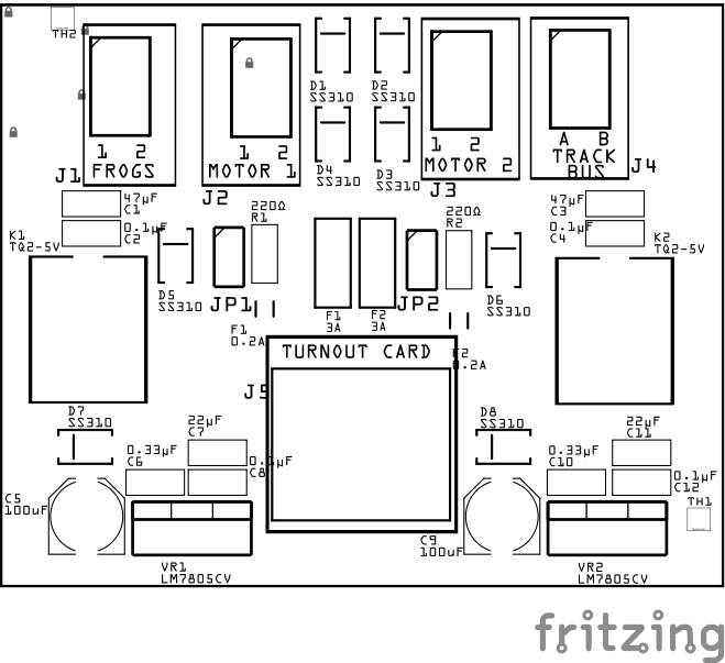
Assembly and Component Placement
This section combines both the component specifications and the assembly instructions to ensure a smooth assembly process. Below is a comprehensive list of components, their placement on the PCB, and orientation details to assist you during assembly.
High-Level Steps for Assembly:
- PCB for the card can be ordered from any PCB fabricator using these Gerber Files.
- Clean PCB with alcohol to remove residue. See Cleaning_PCB for details.
- See also: Soldering Tips
- PCB Components - listing of components used for PCB assembly
- PCB Parts - listing of parts used for PCB assembly
![]()
![]()
| Component Identifier | Count | Type | Value | Package | Purpose | Orientation |
|---|---|---|---|---|---|---|
| Capacitors | ||||||
| C1, C3 | 2 | Capacitor-Ceramic | 47uF | 1206 X7R | Used to smooth voltage/current changes from relay Slow_Motions | None |
| C2, C4 | 2 | Capacitor-Ceramic | 0.1uF | 1206 X7R | Used to reduce voltage spikes from relay coils | None |
| C5, C9 | 2 | Capacitor-Polymer Solid | 100µF | 6.3x5.8mm SMD | Used by 5V voltage regulator for input filtering. | Anode positioned toward PCB top edge |
| C6, C10 | 2 | Capacitor-Ceramic | 0.33 uF | 1206 X7R | Used by 5V voltage regulator for input filtering. | None |
| C7, C11 | 2 | Capacitor-Ceramic | 22uF | 1206 X7R | Used by 5V voltage regulator for output filtering. | None |
| C8, C12 | 2 | Capacitor-Ceramic | 0.1 uF | 1206 X7R | Used by 5V voltage regulator for output filtering. | None |
| Diodes | ||||||
| D1 - D6 | 6 | Diode-Schottky | SS310 | SMD | Circuit protection against flyback from motors and coils. | Position cathode end (white line) to PCB top edge |
| D7 - D8 | 2 | Diode-Schottky | SS310 | SMD | Forces bidirectional motor current to flow only one way to LM7805 voltage regulator | Position cathode end (white line) to PCB left edge |
| Fuses & Protection | ||||||
| F1, F2 | 2 | Fuse-PTC Polymer | JK30, 3A, 16 VDC (or more) | 5.1mm pitch, PTH | Protects from sustained overcurrent conditions on frog | None |
| Connectors | ||||||
| J1 | 1 | JST XH Socket | 2P, 2.54mm | PTH or Spring Term | Connector to turnout frog | Position connection outward |
| J2, J3 | 2 | JST XH Socket | 2P, 2.54mm | PTH or Spring Term | Connector to motor(s) | Position connection outward |
| J4 | 1 | JST XH Socket | 2P, 2.54mm | PTH or Spring Term | Connector to track power rails (Rail A and Rail B) | Position connection outward |
| J5 | 1 | RJ45 socket | 8P8C | PTH | Network cable (CAT5/6) connection from Turnout Card. | Fits only one way |
| Selectors | ||||||
| JP1, JP2 | 2 | Male Header | 2-Pin | PTH | Used to bypass current limiting resistor (R1,R2) to the motor. | None |
| SH1, SH2 | 2 | Jumper Cap (Shunt) | 2.54mm | - | Use JP1-JP2 | None |
| Resistors | ||||||
| R1, R2 | 2 | Resistor | 220Ω | 1206 SMD | Limit current to motor, adjust value based on stall motor requirements. | None |
| Relays | ||||||
| K1, K2 | 2 | Relay | DPST, Non-Latching (Stable) | TQ2-5V (PTH) | Controls track Rail A and Rail B to frog and Point Sense line to ground | Position IC’s small dimple in corner (pin 1) towards PCB top edge |
| Voltage Regulators | ||||||
| VR1, VR2 | 2 | Voltage Regulator | LM7805CV | TO-220, SMD | Provides 5V power to NE555 timer and servo motor(s). | Position heat sink towards PCB top edge |
Tools Required
Safety Precautions
- See Safety Precautions.
Testing and Verification
Visual Inspection
- Initial Check: Examine the board for any obvious issues like missing components, solder bridges, or components that are misaligned or not fully seated.
- Solder Joint Inspection: Use a magnifying glass or a microscope to inspect solder joints. Look for cold solder joints, insufficient or excessive solder, or any shorts between pads.
Functional Testing
-
Supported slow-motion (stall) switch machines (bidirectional):
-
Switch Tender Switch Machine (MicroMark, 12 VDC, slow motion) w/o switch
Note: Use different size resistors to get stall current to be as small as possible
-
Walthers 942-101 Switch Machine $25, (instructions
- Note: Refer to section 4.5 on connecting ‘stall’ motor type of wiring to the 2 POWER pins
-
MP4, MP5 and MP10 Switch Machine by Model Railroad Control Systems
- MP4 - 3rd wire for bidirectional (wiring PDF)
-
-
Note Supported (non-stall motor)
- Tam Valley Singlet Servo and SwitchWright Servo Driver Board (servo controlled)
- MP1 Version 2 Switch Motor
Troubleshooting
Appendences
PCB Specifications
Specifications for the Turnout Slow Motion Switch Machine Breakout Board include:
| Characteristic | Value |
|---|---|
| Output | 9V, 12 VDC1 |
| Max Turnouts | 2 |
| Minimum Current | ~30–180 mA2 |
- Output voltage is determined by the motor output voltage selection found on the Turnout Card.
- About 30mA when relay has been set to switch frog polarity. Max of 180mA when switch machine is moving the points, and relay has been set.
How It Works
The ** Turnout Slow Motion Switch Machine Breakout Board ** is designed to interface with the ** Turnout Card ** to control slow-motion stall motors for managing turnout points, while also controlling the frog polarity based on turnout position. The board enables bidirectional motor control and uses relays to switch the frog between Rail A and Rail B of the track bus, ensuring proper electrical continuity as the turnout moves between the Thrown and Closed positions.
-
Inputs and Outputs Connections:
- Input (Control Signals):
- The board receives control signals from the Turnout Card via two input lines that handle the bidirectional motor control. Based on the Turnout Card motor output selection, motor control signals are 9V or 12 VDC outputs that set the motor’s direction to move the turnout points to either Thrown or Closed.
- Motor Output:
- Two motor output terminals connect directly to the slow-motion stall motor. The motor is driven in one direction or the other depending on the polarity of the control signals.
- The board includes current limiting resistors to control current to the motors. Use the motor’s documentation to determine the correct amount of current to the motor.
- The board also includes optional protection using polyfuse (resettable, PPTCs) on the motor control lines to protect against overcurrent conditions that could damage the driver circuitry.
- Input (Control Signals):
-
Bidirectional Motor Control:
- The Turnout Card controls the motor direction. Depending on the control signal:
- One polarity drives the motor in the direction to set the turnout to the Thrown position.
- The reverse polarity drives the motor in the direction to set the turnout to the Closed position.
- As the control signals are received from the LCC Fusion Node Card firmware, the Turnout Card MCP23017 GPIO switches between high and low states and uses a TC4428 to drive the motor, moving the turnout points to the required position.
- The Turnout Card controls the motor direction. Depending on the control signal:
-
Relays for Frog Polarity Control:
- The Turnout Slow Motion Switch Machine Breakout Board uses a mechanical relay to control the frog polarity. The relay switches the frog’s connection between Rail A and Rail B based on the position of the turnout.
- This ensures that the frog always has the correct polarity based on the turnout’s position, providing smooth operation and preventing short circuits as the train moves through the turnout.
Connections
The purpose of the Turnout Servo Switch Machine Breakout Board and its connectors is to facilitate quick and easy connections between the Turnout Card and a turnout controlled by a servo.
| Component Designator | **Connector Label ** | Connector Type | Connection Number | Description |
|---|---|---|---|---|
| J1 | ACC GND | JST XH, Spring Terminal | GND | Connection to the layouts accessory bus or dedicated power supply (not to DCC). |
| J2 | FROGS | JST XH, Spring Terminal | 1, 2 | Connection to power turnout frogs |
| J3, J4 | MOTOR 1 / MOTOR 2 | JST XH, Spring Terminal | 1, 2 | Connection to switch machine. Note the current is bidirectional. |
| J5 | TRACK BUS | JST XH, Spring Terminal | A, B | Connections to the layout track bus for Rail A and Rail B. Used to power the frog when. If necessary, switch the connections to match the frog to the correct rail. |
| J6 | TURNOUT CARD | RJ45 Socket | 1 - 8 | Refer to Turnout Card’s connection table for the function of each pin |
PCB Protection
| Protected Component | Protection Component | Function | Specifications | Location |
|---|---|---|---|---|
| Entire Circuit | PPTC Polyfuse | Protects from sustained overcurrent conditions by increasing resistance when the current exceeds 0.25A (250 mA). Resets once the fault condition is cleared. | Hold Current: 0.25A Trip Current: 0.5A |
In series with the motor’s Vcc line. Adjust the fuse type to match the max current expected by the stall motor. |
| Track Power | PPTC Polyfuse | Protects from sustained overcurrent conditions by increasing resistance. Resets once the fault condition is cleared. | Fuse Rating: Based on max track current (typically 0.5-3.5A depending on track power). | In series with the track power supply, between the power source and the track. |
| Relay Coils, Stall Motors | Flyback Diode | Protects the circuit from high-voltage spikes caused by inductive loads (relay coils, stall motors) when switching off. | Diode Type: Schottky Max Current: Min 0.5A Reverse Voltage: Min 12 VDC |
Across the relay coil or stall motor terminals (one diode for each direction in bidirectional motor circuits). |
| LM7805CV Regulator | Capacitors (Input/Output) | Stabilizes voltage and reduces noise on the input and output of the voltage regulator. | Input Cap: 0.33µF Output Cap: 0.1µF |
Input cap across the input pin and GND. Output cap across the output pin and GND. |
| Stall Motor | Current-Limiting Resistor | Limits the current flowing through the stall motor to prevent damage or overheating. | Resistor value is determined by the stall motor’s voltage and current rating. | In series with the stall motor, resistor size based on motor specifications. |
| Entire Circuit | Reverse Polarity | Protects the entire circuit against reverse polarity by becoming forward-biased when the power supply is connected backward, effectively short-circuiting the supply and blowing the fuse to protect the circuit. | Diode Type: Schottky Max Current: Min 0.5A Reverse Voltage: Min 12 VDC |
In series with ACC GND |
References
- Preparing a PCB for Soldering
- Solder Tips
- Turnout Motor list: https://dccwiki.com/Turnout_Motors