Turnout Stall Motor Switch Machine Breakout Board Assembly Guide
Table of contents
Table of contents
Introduction
The Turnout Stall Motor Switch Machine Breakout Board, used in conjunction with the LCC LCC Fusion Node Card and a stall motor switch machine (e.g. Circuitron TORTOISE™ slow-motion switch machine or a DCC Concepts Cobalt Turnout Motor Omega Classic), provides both motor control and turnout point position sensing. This breakout board offers a direct plug-in connection to these stall motor switch machines, eliminating the need for additional wiring. Integrated within the LCC Node framework, the Turnout Stall Motor Switch Machine Breakout Board enables control of a turnout based on LCC events received by the LCC Fusion Node Card. It also generates LCC events when the turnout points are thrown or closed.
The Turnout Stall Motor Switch Machine Breakout Board also supports daisy-chaining with a second breakout board using a standard network cable. Each Turnout Stall Motor Switch Machine Breakout Board connects to a Turnout Card, and up to 4 pairs of breakout boards (8 total) can be managed by a single Turnout Card. A single LCC node can support up to 16 Turnout Cards via the LCC Fusion Node Bus Hub, allowing for control of a large number of stall motor switch machines. This design simplifies wiring and ensures efficient communication between breakout boards and the Turnout Card, making it ideal for large layouts with multiple turnouts.
Usage:
This breakout board is for use with 3-wire servo used as a stall motor switch machines. Wiring examples:
| Manufacturer | Product | Breakout Board to Switch Machine Connects | Turnout Card Motor Voltage Selection | Comments |
|---|---|---|---|---|
| Model Railroad Control Systems (MRCS) | Circuitron TORTOISE™ | Connect edge card connector (J1) to switch machine card edge | 9V, 12 VDC | Single connection will connect all 8 contacts of the switch machine |
| DCCconcepts | Cobalt Omega Classic Point Motor (CB1A) | Connect edge card connector (J1) to switch machine card edge | 9V, 12 VDC | Single connection will connect all 8 contacts of the switch machine Cobalt Classic Wiring (PDF) |
TORTOISE™ is a trademark of Circuitron, Inc. All rights reserved. This product is not affiliated with or endorsed by Circuitron.
flowchart LR;
can["CAN Network"];
subgraph layout ["Train Layout"];
n["Node Card"];
c["Turnout Card"];
direction LR;
can <--> n;
n <--> |"GPIO Signal <br/> (high/low)"| c;
c <--> |"Turnout Control <br/> (9 VDC/12 VDC, direction, status)"| bb[Turnout <br/> Stall Motor <br/> Breakout Board];
bb --> |"Switch Machine Control <br> (Bi-Directional Power, Frog Power)"| sm("Switch Machine <br/> (stall motor)");
sm --> |"Frog Power <br/> (Rail A/B)"| frog["Frog"];
sm --> |"Motor Control <br/>(9 VDC/12 VDC, Bi-Directional)"| smotor["Stall Motor"];
sm --> |"Points Staus<br/>(thrown/closed)"| bb;

abus["ACC BUS <br/> (GND)"] --> bb;
tbus["TRACK BUS"] --> bb;
end;
classDef lSalmonStyle fill:#FFA07A,stroke:#333,stroke-width:2px,font-size:24px;
class bb lSalmonStyle;
classDef lightGrayStyle fill:#d3d3d3,stroke:#333,stroke-width:2px,font-size:24px;
class layout lightGrayStyle;
Assembly and Component Placement
This section combines both the component specifications and the assembly instructions to ensure a smooth assembly process. Below is a comprehensive list of components, their placement on the PCB, and orientation details to assist you during assembly.
High-Level Steps for Assembly:
- PCB for the card can be ordered from any PCB fabricator using these Gerber Files.
- Clean PCB with alcohol to remove residue. See Cleaning_PCB for details.
- See also: Soldering Tips
- PCB Components - listing of components used for PCB assembly
- PCB Parts - listing of parts used for PCB assembly
Below is a list of the PCB components used for this card (see diagram before reference):
![]()
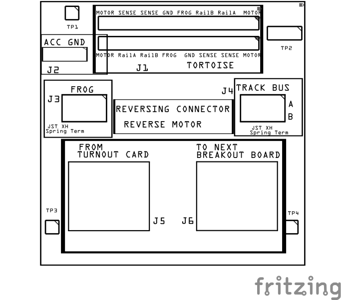
![]()
| Component Identifier | Count | Type | Value | Package | Purpose | Orientation |
|---|---|---|---|---|---|---|
| Connectors | ||||||
| J1 | 1 | Card Edge Connector | 12P (2x6) | 3.96mm, 805 Type A, PTH | Connector for the stall motor switch machine | N/A (can connect to stall machine in either direction) |
| J2 | 1 | JST XH Socket | 2P, 2.54mm | PTH or Spring Terminal | Connector to ACC GND. Note that this GND connection must be connected to the same GND as the LCC Fusion Node Bus (i.e., share the same Ground Plane). | Position connection outward |
<div style="text-align: center;"> 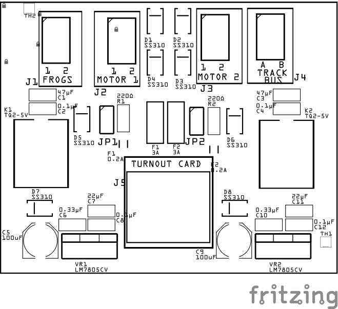 </div><div style="text-align: left;"> </div><div style="text-align: left;"> |
1 | JST XH Socket | 2P, 2.54mm | PTH or Spring Terminal | Connector to turnout frog | Position connection outward |
| J4 | 1 | JST XH Socket | 2P, 2.54mm | PTH or Spring Terminal | Connector to track Rail A and Rail B | Position connection outward |
| J5 | 1 | RJ45 socket | 8P8C | PTH | Network cable (CAT5/6) connection from Turnout Card | Fits only one way |
| J6 | 1 | RJ45 socket | 8P8C | PTH | Network cable (CAT5/6) connection to 2nd breakout board | Fits only one way |
| Test Points | ||||||
| TP1 - TP4 | 4 | Male Header Pins | 1P, 2P | - | Provide connections to the Test Breakout Board | N/A |
Tools Required
Safety Precautions
- See Safety Precautions.
Testing and Verification
Visual Inspection
- Initial Check: Examine the board for any obvious issues like missing components, solder bridges, or components that are misaligned or not fully seated.
- Solder Joint Inspection: Use a magnifying glass or a microscope to inspect solder joints. Look for cold solder joints, insufficient or excessive solder, or any shorts between pads.
Functional Testing
Troubleshooting
- See I2C Trouble Shooting.
Appendences
PCB Specifications
Specifications for the Block Breakout Board include:
| Characteristic | Value |
|---|---|
| Max Stall Motor Switch Machines | 11 |
- The breakout board can be daisy chained to a 2nd breakout board since each of the Turnout Card network cable connections supports 2 breakout boards.
How It Works
The breakout board is connected directly to a stall motor switch machine, allowing bidirectional control in either direction.
Reversing the direction switches the motor contacts, causing the motor to operate in the opposite direction.
Input from the Turnout Card is delivered via the RJ45 socket, which provides both motor control and turnout point status feedback. The network cable supports connections for two switch machines, allowing the second RJ45 socket to be used for daisy-chaining a breakout board for a second switch machine.
All eight of the TORTOISE™ and DCCconcepts stall motor switch machine’s contacts are used as follows:
- Motor Contacts (1 and 8): The Turnout Card provides either 9V or 12 VDC bidirectional power, depending on the requested movement from the firmware. The current is continuous until a direction change is commanded.
- SPDT Switch 1 (2, 3, 4): Connects the TRACK BUS Rails A and B to the turnout’s frog, ensuring the correct polarity depending on the turnout position. Contact 4 is common.
- SPDT Switch 2 (5, 6, 7): Connects the sense lines (RJ45 pins 3 and 4) to ground. As the motor moves the turnout points, this SPDT switch opens and closes, setting the sense lines to either high or low. During movement, the SPDT contacts remain open, causing both sense lines to remain high (default state). Contact 5 is common. The Turnout Card monitors these high/low states to determine the turnout point status. For more information on how the turnout point states are processed, refer to the Turnout Card documentation.
This setup ensures accurate control and feedback of the turnout position, allowing the Turnout Card to manage both the turnout movement and point status in real time.
Refer to the Turnout Card for more details on how the turnout point states are processed.
Connections
The purpose of the Turnout Stall Motor Switch Machine Breakout Board and its connectors is to facilitate quick and easy connections between the Turnout Card and a turnout controlled by a stall motor switch machine.
| Component Designator | **Connector Label ** | Connector Type | Connection Number | Description |
|---|---|---|---|---|
| J1 | SWITCH MACHINE | Edge Connector | 1, 8 | Bidirectional motor connects directly to the Tortoise™ or DCCconcepts switch machine |
| J2 | ACC GND | JST XH, Spring Terminal | GND | Connection to the layouts accessory bus GND connection |
| J3 | FROGS | JST XH, Spring Terminal | 1, 2 | Connection to power turnout frogs |
| J4 | TRACK BUS | JST XH, Spring Terminal | A, B | Connections to the layout track bus for Rail A and Rail B. Used to power the frog when. If necessary, switch the connections to match the frog to the correct rail. |
| J5 | FROM TURNOUT CARD | RJ45 Socket | 1 - 8 | Refer to Turnout Card’s connection table for the function of each pin |
| J6 | TO NEXT BREAKOUT | RJ45 Socket | 1 - 8 | J6 can be used to cable to a 2nd stall motor switch machine |
| TP1 - TP4 | n/a | Male Pins | n/a | Provide connections the Test Breakout Board |
References
- Preparing a PCB for Soldering
- Solder Tips
- Turnout Motor list: https://dccwiki.com/Turnout_Motors