UOD Card Assembly Guide
Table of contents
Table of contents
Introduction
See the How to Use Assembly Guides for detailed instructions.
Introduction
The Ultrasonic Occupancy Detection Card (UOD Card), in synergy with the LCC Fusion Node Card, enables non-contact object detection within configurable distance thresholds. It forms an integral part of the LCC Fusion Project system by interpreting ultrasonic sensor feedback to detect the presence of objects—such as people, scenery elements, or train movement—near the layout.
This integration supports a wide range of automation features, from activating lighting as a person approaches the layout to triggering announcements or other effects based on proximity. By connecting to the UOD Breakout Board, the UOD Card supports up to five sensors using simplified wiring and standardized signal handling.
flowchart LR;
can["CAN Network"];
subgraph layout ["Train Layout"];
  direction LR;
  uod[["UOD Card (16x)"]]
  nodecard[[Node Card]];
  object(("Object (person)"))
  device("UOD Sensor");
  bb[[UOD Breakout Board]];

  object -.->|"Sound Waves"|device
  device --> |"Analog signal"|bb;
  bb -->|"Analog signal"| uod;
  uod -->|"GPIO Output <br/> High/Low"| nodecard;
  nodecard -->|"LCC Event <br/> (occupied/unoccupied)"| can;
end;
classDef lSalmonStyle fill:#FFA07A,stroke:#333,stroke-width:2px,font-size:20px;
class uod lSalmonStyle;
classDef lightGrayStyle fill:#d3d3d3,stroke:#333,stroke-width:2px,font-size:24px;
class layout lightGrayStyle;
Assembly and Component Placement
This section combines both the component specifications and the assembly instructions to ensure a smooth assembly process. Below is a comprehensive list of components, their placement on the PCB, and orientation details to assist you during assembly.
High-Level Steps for Assembly:
- PCB for the card can be ordered from any PCB fabricator using these Gerber Files.
- Clean PCB with alcohol to remove residue. See Cleaning_PCB for details.
- See also: Soldering Tips
- PCB Components - listing of components used for PCB assembly
- PCB Parts - listing of parts used for PCB assembly
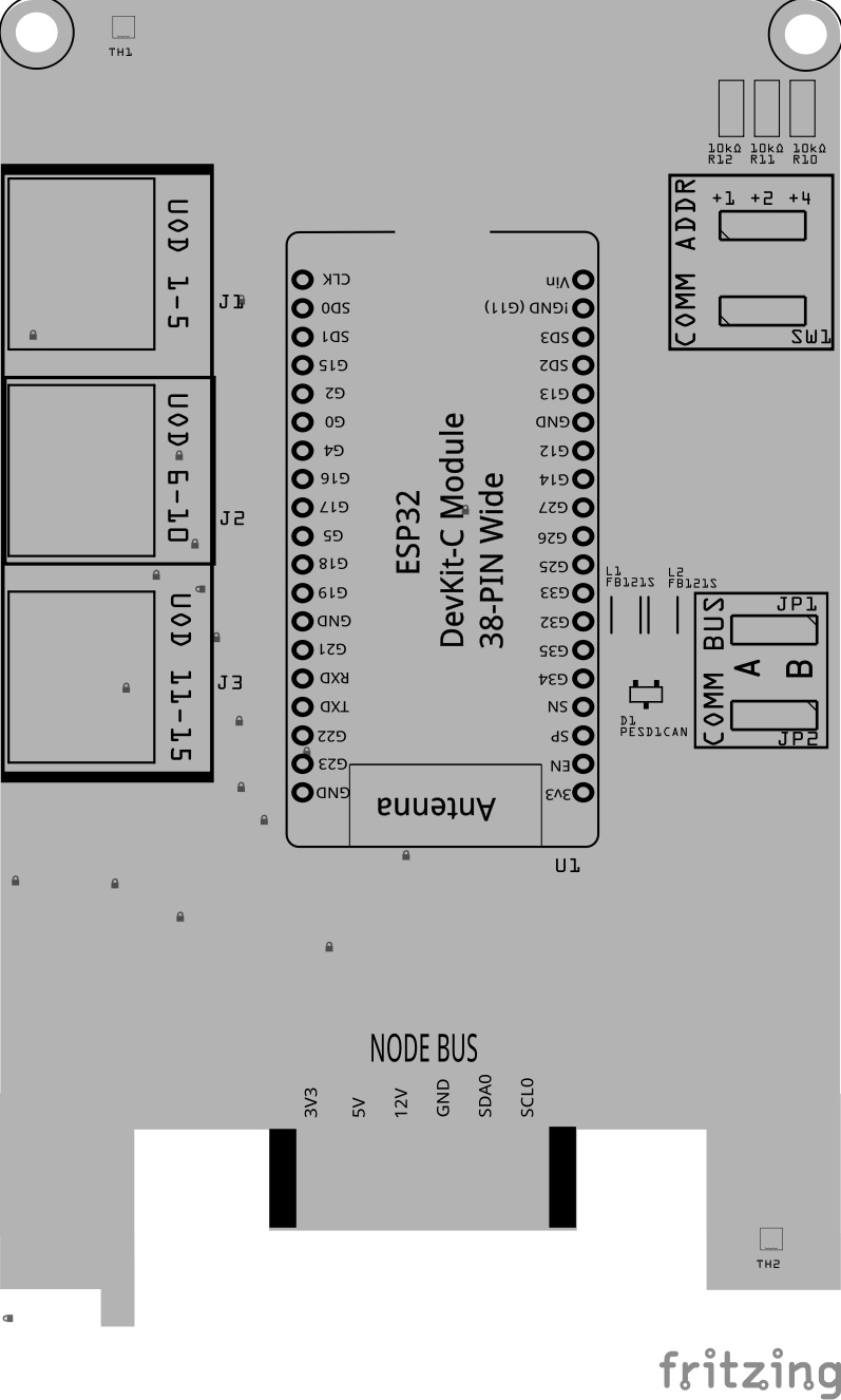
Below is a list of the PCB components used for this card (see diagram before reference):
![]()
![]()
| Component Identifier | Count1 | Type | Value | Package | Purpose | |
|---|---|---|---|---|---|---|
| Capacitors | ||||||
| C1 | 1 | Capacitor-Ceramic | 0.1uF | 1206 SMD | Decoupling and noise reduction capacitor for I2C display | None |
| C2 | 1 | Capacitor-Ceramic | 10uF | 1206 SMD | Decoupling and noise reduction capacitor for I2C display | None |
| Diodes | ||||||
| D1 | 1 | ESD Diode | PESD1CAN | SOT-23 SMD | I2C data bus electrostatic discharge (ESD) protection. | None |
| Filters & Noise Suppression | ||||||
| FB1, FB2, FB3 | 3 | Ferrite Bead | BLM31PG121SN1L | 1206 SMD | Noise suppression for I2C data lines and I2C display | None |
| Connectors | ||||||
| J1, J2, J3 | 3 | RJ45 Socket | 8P8C | PTH | Network cable (CAT5/6) connection to UOD Breakout Boards | Fits only one way |
| J4 | 1 | Female header | 2-Pin, 2.54mm | PTH | OLED Display Connection | None |
| Selectors & Indicators | ||||||
| LED1 | 1 | LED (Red) | 2 mA | 1206 SMD | Object Detected Indicator | Reference back of LED, position cathode towards PCB left edge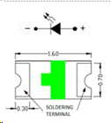 |
| LED2 | 1 | LED (Red) | 2 mA | 1206 SMD | 5V Power Indicator | Reference back of LED, position cathode towards PCB left edge |
| JP1, JP2 | 2 | Male Header | 3P, 0.1” spacing | PTH | Used for COMM BUS selection (I2C hardware bus) for either BUS A or BUS B. Must match LCC Node configuration (CDI). | None |
| SH1, SH2 | 2 | Jumper Cap | 2.54mm | N/A | Used with I2C Bus and Vcc selections. Recommend tall caps for ease of use. | None |
| SW1 | 1 | DIP / Slide Switch | 3P, 2.54mm | N/A | Used for COMM ADDR selection (I2C address offset, 0-7). | Position ON towards PCB top edge |
| Resistors | ||||||
| R1-R3 | 3 | Resistor | 10kΩ | 1206 SMD | Limits the current to SW1 and ESP32 for the I2C address | None |
| R4, R5 | 2 | Resistor | 10k Ω | 1206 SMD | Voltage Divider (high/low ends) | None |
| R6 | 1 | Resistor | 1kΩ | 1206 SMD | Current limiting for LED | None |
| R7 | 1 | Resistor | 3.3kΩ | 1206 SMD | Current limiting for LED | None |
| ICs | ||||||
| U1 | 1 | ESP32 Module | ESP32 DevKitC | DevKitC | Processes I2C text messages from the Node Card and sends player commands via UART | Position USB connection to PCB top edge |
| 1 | OLED Display | SSD1309, SSD1306 | 4-Pin, I2C | Display serial messages from firmware | Refer to silk screen of OLED and card, display extends out from card. |
Tools Required
For a list of recommended tools, refer to List of recommended tools.
Safety Precautions
- See Safety Precautions.
Testing and Verification
Configure the UOD Card:
-
Select the
COMM BUSby positioning (2) Jumper Caps on eitherAorBmale header pins (JP1, JP2) -
Select the
COMM ADDRESSswitch (SW1) by sliding each of the 3 switches to either theONorOFFposition. Setting a switch to ON increments the address by 1, 2, or 4 for an address range of 0 to 7. Up to 8 devices can then be configured forAand 8 forB.
The following test and verifications of the card should be performed after a through inspection of the card’s soldering. Check all of the PTH component pins and SMD pads. Make sure there are no solder bridges between pins and pads.
Visual Inspection
-
Initial Check: Examine the board for any obvious issues like missing components, solder bridges, or components that are misaligned or not fully seated.
-
Solder Joint Inspection: Use a magnifying glass or a microscope to inspect solder joints. Look for cold solder joints, insufficient or excessive solder, or any shorts between pads.
-
Component Orientation: the IC’s are correctly oriented according to the PCB silkscreen or schematic.
Connectivity Testing
![]()
Power-Up Tests
- Assembly a tested to the LCC Fusion Node Card.
- Apply Power to the Power Module and verify the following:
- Check for Hot Components: Feel for components that are overheating, which could indicate a problem like a short circuit or incorrect component.
Functional Testing
Functional testing of the card can be performed after completing the power-up testing. Testing consists of testing network communiations, followed by the sensing of current in a layout track block.
HW Communications Testing
Communications testing verifies the LCC Node can communicate with the UOD Card’s I2C IC via the Node Bus Hub connections. This is performed using the LCC Fusion Node Card’s testing firmware and a serial monitor.
-
Insert the UOD Card into a Node Bus Hub along with a LCC Fusion Node Card.
-
Install LCC Fusion Project firmware that includes serial monitor for testing.
-
Verify that the I2C connection between the LCC Fusion Node Card and the UOD Card work.
See Testing I2C Cards for details on how to test the communications for a I2C enabled card.
Provisioning the Card
- See Provisioning a Card.
Troubleshooting
- See I2C Trouble Shooting.
Appendences
PCB Specifications
Specifications for the card include:
![]()
| Characteristic | Value |
|---|---|
| Maximum UOD Sensors | 5 |
| Maximum Block Breakout Boards | 2 |
| Maximum Cards per LCC Fusion Node Cluster | 161 |
- The LCC Fusion Node Cluster supports up to 16 cards, distributed across two I2C hardware buses, with a maximum of 8 cards per bus.
- Note: This total includes all cards using the I2C address range of
0x20(MCP23017 IC).
- Note: This total includes all cards using the I2C address range of
How It Works
The UOD Card uses an onboard ESP32 microcontroller to manage up to five ultrasonic sensors connected through the UOD Breakout Board. Each sensor sends a digital echo pulse whose width corresponds to the distance from the sensor to the nearest object.
Sensor Polling Cycle
- The ESP32 continuously cycles through all five sensors in a 60 ms loop.
- It sends a brief trigger pulse to initiate each sensor and then measures the duration of the echo pulse to calculate distance.
- Each sensor is triggered and measured independently to avoid signal interference.
Detection and Thresholding
- A detection is registered when the measured distance falls within a configurable threshold range (e.g., 5 cm to 150 cm).
- When detection occurs, the ESP32 sets a status flag for that sensor line.
Node Communication via I²C
- Once detection is recorded, the UOD Card communicates the result to the Node Card using a custom I²C protocol.
- Communication occurs over the Node Bus Hub, allowing addressable multi-card connectivity.
- The I²C address of the UOD Card is configurable (range:
0x50to0x57), and the card also supports bus selection (A or B).
Firmware Integration
- The Node Card firmware includes built-in support for the UOD Card protocol.
- When a detection event is received via I²C, the Node Card generates a corresponding LCC event on the network.
- These events can then trigger lighting, sound, animation, or other layout responses.
Summary of Data Flow
- Sensor → Sends echo pulse
- ESP32 → Measures pulse, applies detection threshold
- UOD Card → Sends sensor state over I²C
- Node Card → Converts detection into LCC event
Connections
The purpose of the UOD Card is to provide detection of track block occupancy by detecting current.
![]()
| Component Designator | Connector Label | Connector Type | Connection Number | Description | | ——————– | ——————– | ————– | ——————— | ———————————————————— | | J1, J2 | UOD DEVICES | RJ45 Socket | 1/2, 3/4, 5/6, 7/8 | Use 1 or 2 network cables to connect to the **Block Breakout Board ** which connects to the track blocks. |
PCB Protection
To ensure the reliable operation and longevity of your UOD Card, several protection components have been integrated. These components safeguard the UOD Card from overcurrent, voltage spikes, and electrical noise. Below is a brief overview of each protection element and its role:
![]()
| Protected Component | Protection Component | Function | Specifications | Location |
|---|---|---|---|---|
| I2C Lines from LCC Fusion Node Bus Hub | Ferrite Bead BLM31PG121SN1L | Provides high-frequency noise suppression on the I2C lines. | Impedance: 120 ohms at 100 MHz | In series with the SDA and SCL lines of the I2C bus |
| I2C Lines from LCC Fusion Node Bus Hub | ESD Protection Diode PESD1CAN | Protects the I2C lines from electrostatic discharge and voltage spikes. | Reverse Stand-off Voltage (Vr): 24 VDC Clamping Voltage (Vc): 40 VDC |
Across the SDA and SCL lines from the card’s edge connector to GND, near the ESP32. |
References
-
RJ45 Mapping (UOD Card)
The UOD Card receives 8 lines via its RJ45 input from each of the (3) UOD Breakout Boards. These include shared power lines, a common trigger line, and individual echo return lines from each the (up to 15) sensors. The onboard ESP32 controls the TRIG line and reads the ECHO lines to calculate distances.
RJ45 Line Signal Name Direction Connected To ESP32 Pin Purpose Notes L1 TRIG Output Breakout GPIO_X Sends trigger pulse to sensors Shared by all 5 sensors L2 S1 (Echo 1) Input ESP32 GPIO_Y1 Echo pulse input from Sensor 1 Pulse width = distance L3 S2 (Echo 2) Input ESP32 GPIO_Y2 Echo pulse input from Sensor 2 L4 S3 (Echo 3) Input ESP32 GPIO_Y3 Echo pulse input from Sensor 3 L5 S4 (Echo 4) Input ESP32 GPIO_Y4 Echo pulse input from Sensor 4 L6 S5 (Echo 5) Input ESP32 GPIO_Y5 Echo pulse input from Sensor 5 L7 5V Output Breakout — Power supply for sensors Shared L8 GND Output Breakout — Power ground for all sensors Shared - ESP32 Firmware Configuration Reference (UOD Card)
The UOD Card firmware uses the ESP32 to poll multiple ultrasonic sensors and communicate proximity detection events over I²C to the Node Card. The table below summarizes pin assignments and configuration parameters used in the firmware:
Function Configuration Details I²C SDA Pin GPIO12Shared between Bus 0 or Bus 1 (configurable on card) I²C SCL Pin GPIO14Shared between Bus 0 or Bus 1 (configurable on card) I²C Address Range 0x50–0x57Controlled by GPIO-based address pins I²C Address Pins GPIO27,GPIO26,GPIO253-bit binary address selection (ADDR0–ADDR2) TRIG Pin (Shared) GPIO15Single trigger line for all sensors Number of Sensors 15Max sensors handled by firmware (expandable for testing) Echo Pins (0–14) {36, 2, 0, 4, 16, 17, 5, 18, 19, 21, 3, 1, 22, 23, 34}Connected directly to sensor echo outputs Measurement Interval ~60 ms per loop Continuous round-robin polling Sensor Library HCSR04.hManages timing of echo pulse measurement