Subjects: Assembly Guides , Automation , Hardware , Signaling
Use Cases: Node Cluster Setup , PCB Design & Assembly
USB-CAN Adapter for Windows
Table of contents
Introduction
This document provides a comprehensive guide on setting up a USB to CAN adapter, specifically the CANable device, for Windows users. Aimed at bridging the gap between your computer and CAN networks, this manual covers the essentials from acquiring a CANable device, updating its firmware to slcan, establishing the hardware connection, configuring JMRI software, to testing the connection with your LCC Node. Whether you’re integrating with JMRI for model railroad automation or any other CAN network application, this guide ensures a smooth setup process, enhanced by illustrative images and step-by-step instructions to facilitate your understanding and implementation.
The Power-CAN Card is specifically designed to support the attachment of the USB-CAN Adapter using a USB cable.
flowchart LR;
computer["Computer"];
n["Node Card, or <br/> Power-CAN Card"];

subgraph layout ["Train Layout"];
direction LR;
computer --> |"USB Plug"| adapter["USB-CAN Adapter"];
adapter --> |"CAN Network <br/> (network cable)"| n;
end

classDef lSalmonStyle fill:#FFA07A,stroke:#333,stroke-width:2px,font-size:24px;
class adapter lSalmonStyle;
classDef lightGrayStyle fill:#d3d3d3,stroke:#333,stroke-width:2px,font-size:24px;
class layout lightGrayStyle;
For other terms, please refer to the full Terminology Guide.
Acquiring a USB-CAN Adapter (aka. CANable Device)
- Purchase a CANable Device, an open-source hardware that serves as a USB to CAN adapter, essential for connecting to CAN networks.
- Ensure the device either:
- Comes pre-installed with slcan firmware (instead of Candlelight firmware), or
- Is capable of entering DFU Download mode, enabling firmware updates from Candlelight to slcan firmware (detailed below).
- Find a CANable device by searching ‘ CANable’ on AliExpress: https://www.aliexpress.us/w/wholesale-canable.html?spm=a2g0o.home.search.0
Firmware Update to slcan
To use the CANable device with JMRI, it must be recognized as a virtual COM port by Windows, requiring slcan firmware.
Follow these steps to update your CANable device to slcan firmware, ensuring compatibility with JMRI:
- Switch to DFU Mode:
- Each type of CANable adapter has a unique method of entering into DFU Mode which allows for updating the adapter’s firmware. To install the slcan firmware, the adapter must be placed into DFU mode before connecting the adapter via USB cable to the Windows computer.
- Using your adapter’s documentation for updating the firmware, enable DFU (Device Firmware Update) Mode by using one of the following methods:
- small dip switch located on the adapters PCB with two positions; DFU mode and normal operations mode.
- shorting out 2 pins (DFU and 3V3)
- holding the DFU button during while inserting the adapter into a computer USB port
- Chrome Preparation for Device Recognition:
- Execute the ImpulseRC Driver Fixer to allow Chrome to detect the device: https://canable.io/utilities/ImpulseRC_Driver_Fixer.exe
- Updating the USB-CAN Adapter (CANable) Firmware:
-
Utilize the CANable.io firmware updater utility to update the adapter firmware to slcan. The firmware update is performed directly through this webpage: CANable Firmware Updater.
- Switch the adapter to DFU mode and connect it to the USB port of a Windows computer.
- Access the link above and choose a slcan version from the dropdown menu.
- Ensure the device is recognized; if not, confirm it is in DFU mode.
- Click the
Connect and Updatebutton to initiate the firmware update. - In the subsequent popup, select
STM32 BOOTLOADER - Pairedand clickConnect. - Choose the device’s name from the displayed list to proceed.
- A message stating
Erasing DFU device memorywill appear; wait during this process. Copying data from browser to DFU devicewill display next; please wait as the firmware transfers.- A confirmation message,
Wrote 27332 bytes, indicates the firmware has been successfully updated. - Click
Disconnect. - Reset the adapter to exit DFU mode and return to normal operation.
-
- Return to Normal Operating Mode:
- If a switch was utilized for entering DFU Mode, revert the CANable device to its regular (Work) mode after the update.
USB-CAN Adapter Connection
Depending on your LCC Fusion configuration, there are multiple ways to connect a CANable device to the project.
| LCC Fusion Card | CAN Connection | Wiring |
|---|---|---|
| Power-CAN Card | CAN INPUT 1,2 | Connect CANable CAN-H & CAN-L to CAN INPUT. |
| Power-CAN Card | CANable Module1,3 | Connect CANable CAN-H & CAN-L to CAN INPUT. |
| Node Card | CAN INPUT 1, 2 | Connect CANable CAN-H & CAN-L to CAN INPUT. |
| Node Card | CAN BUS (RJ45) 4 | Connect wires 1-3 of CAT cable to CANable device. |
- GND is not required.
- For protection, use an isolated CANable device to keep the computer’s network separate from LCC Fusion’s CAN network.
- Provides isolation with high-speed optocouplers.
- See below for network cable modification.
CAT Cable Modification
The following describes how to modify a network cable to connect from the Node Card CAN BUS RJ45 socket to the CANable device.
-
Remove the RJ45 plug from one end of the cable to reveal the 8 internal wires.
-
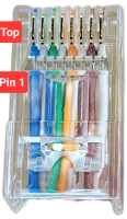 On the opposite end, identify the first three wires by looking at the RJ45 plug’s back with the tab facing downwards.
 -
 Connect these to the USB-CAN adapter:
Network Cable Wire USB-CAN Adapter Screw Terminal 1 (leftmost wire, from left to right) CAN-L 2 (second wire) GND 3 (third wire) CAN-H
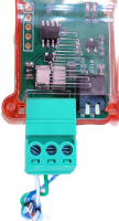
Final Hardware Setup Steps
Complete the setup by connecting the modified network cable to the USB to CAN device’s screw terminals and establishing the connection to the LCC Node as follows:
- Activate the CAN termination switch to the ON position for this adapter since it is located at one end of the CAN network. It’s crucial to also configure a CAN termination at the network’s other end, which is most likely to be on an LCC Node, to ensure proper network functionality.
 Plug the USB to CAN device into a USB port on the computer.
- Insert the cable’s RJ45 connector into one of the two CAN network ports on the LCC Node.
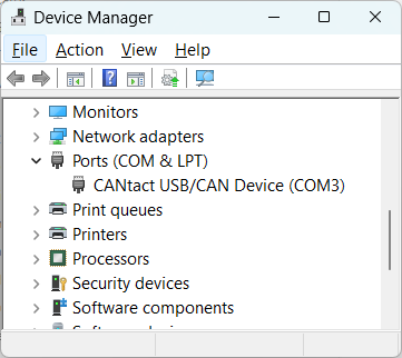
- To determine the Windows COM port used by the adapter open the Windows Device Manager and view the COM ports. The device CANtact USB/CAN Device (COMx) should be shown, along with the COM port. Use this COM port below when configuring JMRI.
-
Note that ‘modern’ versions Windows will automatically find/install the device driver required to support the USB to CAN device. For older versions of Windows, following the information found at https://canable.io/getting-started.html#drivers
JMRI Configuration
To integrate JMRI with the CAN network through a USB to CAN adapter, execute the following instructions:
-
Launch the JMRI DecoderPro application from your Windows system.
-
Navigate to
Edit->Preferencesfrom the main menu of DecoderPro. -
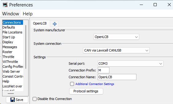 Configure a new connection by applying the following parameters:
-
System Manufacturer: OpenLCB -
System Connection: CAN via Lawicell CAN/USB -
Settings:Serial Port: COMx(Identify this as the Windows-assigned port upon connecting the USB-CAN device)Connection Prefix: M(default setting)Connection Name:[Your chosen name]
-
-
Finalize your settings by clicking the
Savebutton located at the bottom-right corner of the Preferences-Connections window.
Test Connection
After restarting JMRI Decoder Pro, verify the connection spanning from the computer, through the adapter, to the CAN network. This verification can be accomplished by choosing the OpenLCB tab from the top menu, followed by Configure Nodes. Every LCC Node within the CAN network should be visible in the Network Tree dialog.