Creating Cables for Plug & Play Layout Automation


Introduction
As a model railroading enthusiast, you might find that the intricacies of layout wiring have evolved considerably. What started with simple 2-wire connections for AC/DC tracks has blossomed into elaborate setups featuring multi-block systems and wiring for an array of accessories like buttons, switches, turnouts, and lights. Nowadays, we’re even integrating full-scale automation, bringing sound, light, and motion to our miniature worlds.
Embracing the NMRA’s LCC standards for layout control and automation introduces a new level of complexity, with numerous LCC Nodes connecting to various input/output devices arranged in clusters or though out the layout.
Wiring a model train setup can swing between deeply satisfying to mildly exasperating. It’s a meticulous dance of tracking wires, tagging them for identification, and the ceaseless cycle of connecting, disconnecting, and adjusting. My background as a software engineer, with a penchant for constructing my home networks and exposure to large data centers, has taught me one thing: the elegance of network cables. These aren’t just for internet connections; they’re now being used for sound, video, and connecting electronic devices.
Inspired by the simplicity of data center cabling, I’m integrated the same approach into my model railroad layout automation using LCC. Utilizing CAT5 or CAT6 cables to link LCC Nodes turned a complex task into something as simple as when connecting a computer to a router. This plug-and-play method, complemented by RJ45 sockets on all I/O boards, significantly streamlined the process.
Throughout my journey, I’ve fashioned several custom network cables, but as my LCC automation project expanded, efficiency became key. Below, I’ll share the tools and methods that have made cable creation for my layout both swift and satisfying.
Supplies
Below is a list of the tools and supplies I’m currently using to create cables. To help reduce costs, I make use of AliExpress for most of my supplies:

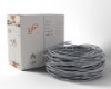
Network Cable - I’ve decided to use CAT6 network cables for several reasons. The cost and availability in last few years make CAT6 a very viable option over the previous CAT 5 or CAT5e generation of cables. The CAT6 standard requires the cable to use a 23awg wire instead of 24awg used in CAT5 cables, providing less of a voltage drop. For example 1A of current thru a 30ft CAT6 will have about a 1.2V drop vs 1.5V drop using CAT5. Also, I found out that the bare wire is stiffer and thus inserts into the RJ45 plugs easier. Note that the cable is less flexibly.

Network Cable Plug - When creating custom cables to be used for plug and play purposes, plugs need to be added to both ends of the cable for connecting to the RJ45 sockets found on the PCB. When purchasing a plug, ensure that get a ‘passthrough’ stype, allowing you to push the wires thru the plug and then cutting. Most plugs nowadays are this type. Both shield and unshielded plugs will work fine. Make sure they are compatible with the cable type to be used (CAT5 or CAT6). CAT6 requires the holes to be 1.08mm in diameter.

Network Cable Tester - Used to verify cable connections and wiring. Plug both ends of network cable into the tester and turn on. Each wire connection is verified. Model show can be separated into two pieces to check installed cables. Network crimpers may also include a built-in tester for convenience.

Network Cable RJ45 Boot - the use of rubber protection boots on the cable ends is optional. Boots are useful to prevent damage to the plug and unintended disconnects from a socket Boots can also be used to help color code your cable ends, making cable identification and tracing under the layout easier.

Clamps - I found the use of 1 or 2 hemostat clamps to be very useful in the holding the 8 wires and maintaining their organization while inserting them into the plug.

Hair Comb - the use of a comb inserted upside down in a block of wood provides a simple way of managing the wires. Start by stacking the wires vertically in the desired order, then applying the clamp on the wire stack, next to the comb. Pulling the clamp upward removes the clamped wires from the comb and provides a ‘handle’ to hold wires, while maintaining their order.
Clearing Tool - a 1mm (0.040”) wire, rod, or drill bit used to clear the eight holes in the plug. This clears possible debris and insures the metal pin is not obstructing the wire when it gets inserted later.
Crafting Ethernet Cables
Outlined below is a detailed cable assembly process I’ve refined using the aforementioned materials. This is covered in a short video.
- Preparing the Plug: I’ve found that CAT wires may resist sliding into plug holes. Running a 1mm wire, drill bit, or rod through each hole helps clear obstructions and insure lock pin is clear of the how. Optionally, you can create a tool to do this more efficiently. Cut 8x 1” pieces from a 1mm rod and glug them into a spare RJ45 plug. Make sure to place the glue inside of the plug, with the 8x wires evenly protruding the plug tip by 0.5”. After the glue has set, push the tool into a plug, tip to tip, to clear all 8 holes at once.
- Preparing the Cable:
- (Optional) Slide two boots onto the cable.
- Use the crimping tool to trim back the cable shield about 2.5 inches, then remove the shielding.
- Eliminate any filler thread, leaving only the eight wires.
- Untwist and straighten the wires. Pressing them against a screwdriver with your thumb and pulling them out will quickly straighten the wires. Do this multiple times until the wires all untwisted and straight.
- Arranging the Wires:
- Fix a metal comb upside down on the workbench, embedding it in a block of wood.
- Align the eight wires vertically between two of the comb’s tines. The sequence is arbitrary for the first set of wires.
- Using different tines on the comb, stack the wires from the other end of the cable. Ensure the wire sequence is identical to the first set of wires.
- Inserting the Wires into the Plug:
- With a hemostat, clamp one wire set about 1.5 inches from the end.
- Trim the clamped wires evenly with the crimping tool, ensuring a clean, uniform cut.
Wrapping Up
In conclusion, creating custom cables tailored to your specific layout can significantly simplify and reduce the expenses involved in wiring for automation. The convenience and reliability of network cables, which can quickly and securely connect eight wires, can greatly diminish the time spent working under the layout. Additionally, employing color-coded cables and using cable tags enhances both the ease of identifying different connections and the process of documenting your layout’s wiring setup.
Don’t forget to check out the accompanying video for a rapid and effective demonstration on crafting and testing a custom cable for your layout. This brief guide will show you just how straightforward and efficient the process can be!