Terminology
Table of contents
Table of contents
- Terminology
- Introduction
- LCC Fusion Project Terms
- LCC Fusion Connect Terms
- LCC Fusion Connect Hardware
- Audio Card
- Battery Card
- BLVD Breakout Board
- Block Breakout Board
- BOD Card (Block Occupancy Detection)
- BLVD Card
- DC Motor Breakout Board
- Digital I/O Card
- Node Bus Hub
- Node Card
- Output Card
- POD Card
- Power-CAN Card
- PWM Card
- Quad-Node Card
- Relay Breakout Board
- Signal Masts Breakout Board
- Sound Card
- Stepper Motor Breakout Board
- SuperMini I/O Status Shield
- Turnout Card
- Turnout Servo Switch Machine Breakout Board
- Turnout Slow Motion Switch Machine Breakout Board
- Turnout Stall Motor Switch Machine Breakout Board
- Turnout Twin-Coils Switch Machine Breakout Board
- USB-CAN Adapter
- NMRA LCC Network Terms
- Model Railroad Automation Terms
- Hardware and Software Terms
- Adapter
- Amplifier
- Audio Signal
- Bridge Rectifier
- Bus
- CAN Termination
- CANable
- Charging Circuit
- Cleaning PCB
- Component
- Crowbar Protection with Fuse
- Current Limiting Resistor
- Decoupling Capacitor
- Card Card Connector
- ESD Protection Diode
- Fast Blow Fuse
- Ferrite Bead
- Flyback Diode
- FSR
- Galvanic Isolation
- GPIO Expander
- Common Ground
- I2C Bus
- I2C
- I2S
- Jumper
- LDR
- Li-Po
- MCP23017
- Network Cable
- Optocoupler
- Polyfuse
- Pull-up
- PWM
- Shield
- Shunt
- Stencil
- Supermini
- TVS Diode
- Voltage Glitch
- Voltage Divider
- Zener Diode
- Electrical Components
- 6N137 {#6n137}
- 74HC00 {#74hc00}
- 74HC4051D {#74HC4051D}
- 74HCT14D {#74hct14d}
- ACS712
- ADS1115 ADC
- AT24C02
- BLM31
- BSS138
- GL5528
- IRLML6402 MOSFET
- IRLZ44N
- KBL406
- LM7805CV
- L7812CV
- LM1117-3V3
- LM2596S-ADJ
- LM393
- LM358
- M54562FP
- MAX98257A
- MB6S
- MCT6H
- MCP23017
- MCP7383T
- MFRC523
- NE556
- PCA9515A
- PCA9685
- PESD1CAN
- PT204
- RV24YN20S
- SMAJ5A
- SMBJ18A
- SN65HVD233DR
- SN74HCT14
- SS310
- TB6612FNG
- TBD62083A
- TC4428
- TQ2-L2-12V
- TQ2-L-5V
- TQ2-5V
- Troubleshooting and Support Terms
- Appendix and References
Introduction
- Brief overview of the importance of understanding specific terms and acronyms used in the LCC Fusion Project.
- Statement on how this glossary aids in better understanding the documentation and the project as a whole.
LCC Fusion Project Terms
CAN Network
Controller Area Network (CAN)
The Controller Area Network (CAN) is a robust communication protocol used for real-time data exchange between microcontrollers and devices. Originally developed for automotive systems, it is now widely used in various industries for its reliability, efficiency, and error-checking capabilities. CAN allows multiple devices to communicate on the same network without a host computer. A CAN Network can be wired or wireless. Wired CAN uses 2-wires to form the network, while wireless CAN can be achieved using WiFi or Bluetooth.
LCC Fusion Project
The LCC Fusion Project is a comprehensive system designed for automating and controlling model railroads using the Layout Command Control (LCC) protocol. It integrates various hardware components like the LCC Node and I/O cards with software tools to enhance the realism and operational efficiency of model railroad layouts.
LCC Fusion Cards
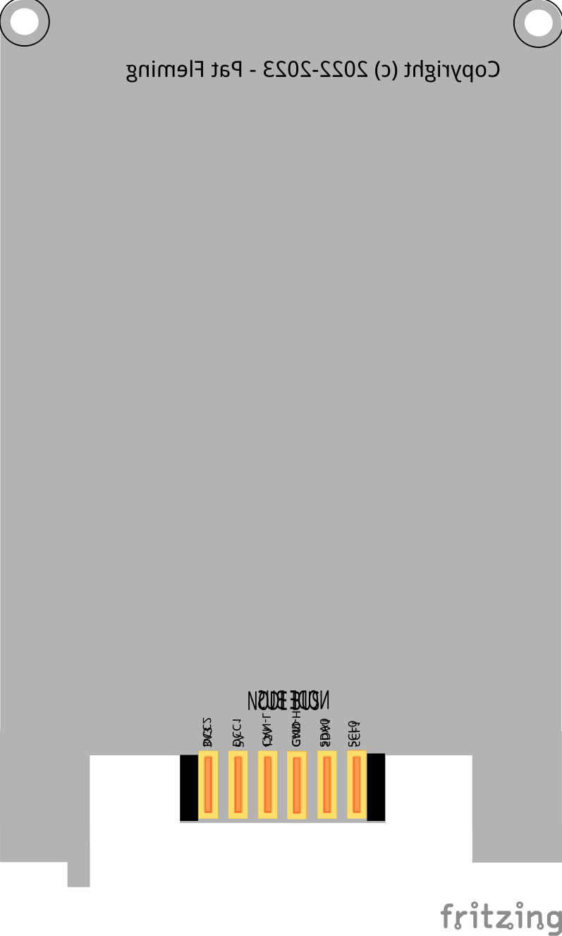 Each card is design to a standard form of width, height, holes for mounting, positioning key, and 12 card edge pads (see pic on right). This design enables the cards to be installed in card edge connectors mount on the Node Bus Hub, ensuring power and communication connects with the Node Card (also installed in the same Node Bus Hub). A positioning key at the bottom of the card insures the card is inserted into the Node Bus Hub with the correct orientation.
| PCB Layer | 1 | 2 | 3 | 4 | 5 | 6 |
|---|---|---|---|---|---|---|
| Top | 3V3 | 5V | 12 V | GND | SDA0 | SCL0 |
| Bottom | SCL1 | SDA1 | CAN-H | CAN-L | DCC1 | DCC2 |
LCC Fusion Breakout Boards
Breakout boards are PCBs designed to be placed close to I/O devices, typically under the layout. They provide fast and simple connections to Cards through the use of RJ45 sockets, allowing Network Cable to link to the corresponding Card. Most breakout boards are sized to fit into PCB housings, are DIN mountable, and feature holes for 3mm screws or standoffs.
Breakout Boards have specialized connectors and labeling for direct connections to specific I/O devices. For example, the Block Breakout Board is used with the BOD Card, facilitating direct connections to track blocks for block occupancy detection. This allows for streamlined wiring and reliable communication between the I/O devices and control systems.
Node Bus
The Node Bus is a key part of the LCC Fusion Project, designed to connect Node Cards and their I/O cards, ensuring they can communicate and receive power properly.
This bus system specifies the types of connections needed, their purposes, and where they should be placed on a PCB. Essentially, the Node Bus makes sure Node Cards and Input Cards can work together smoothly, providing both the power and the means for them to talk to each other.
There are twelve (12) specific connections outlined for the Node Bus:
- Power Lines (GND, 3V3, 5V, 12 V) for different power needs.
- CAN Bus Lines (CAN-L, CAN-H) for LCC communications.
- I2C Lines for two sets of hardware buses (SDA0, SCL0, SDA1, SCL1) for data communication.
The setup of the Node Bus is guided by the LCC Fusion Framework’s design, including where the connection pads are located on the edges of the cards.
Node Cluster
A Node Cluster is a physical configuration that consists of at least a Node Card and optionally additional cards connected via a Node Bus Hub. A Node Cluster closely equates to an LCC Node as it will appear a configuration tool as an LCC Node. Note that one or more Node Cards can be configurated within a Node Cluster.
Virtual Node Cluster
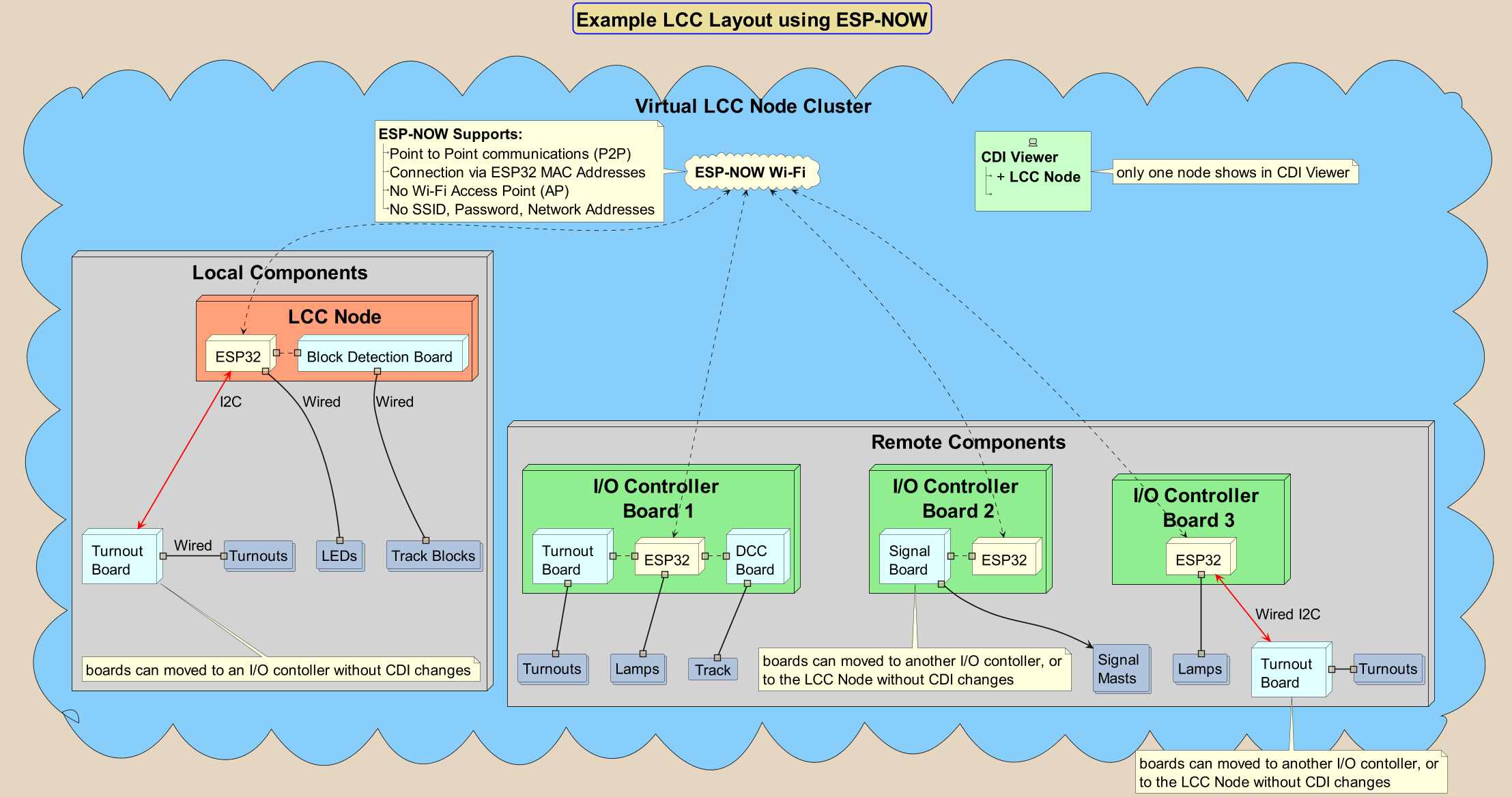 A Virtual LCC Node Cluster is a configuration utilizing a virtual connection between its Node Card and other LCC Fusion Connect cards. A Virtual LCC Node Cluster is an alternative to creating multi-Node clusters by allowing a single LCC Node to wirelessly perform I/O communications with multiple I/O cards dispersed throughout a layout. This allows a scale-up of I/O without the complexity of managing multiple LCC Nodes.
The virtual cluster consists of at least a Node Card connecting wirelessly to an I/O Controller Card. The I/O Controller Card can provide local I/O and/or thru the use a Node Bus Hub can perform I/O to additional cards.
I/O boards can be relocated, minor rewiring and no configuration changes.
The Node Card utilizes ESP-NOW Wi-Fi technology to extend I/O wirelessly to I/O cards, reducing wiring, and providing flexibility in moving cards. ESP-NOW provides Wi-Fi without the use of an access point, ssid, or password.
Node Card Types
Within a Node Cluster, there are two types of Node Cards, a single Primary Node Card and one or more Secondary Node Cards, as follows:
- Primary Node Card: This is the first Node Card you’ll connect to your system using a Node Bus Hub. It plays a pivotal role by being the initial point of contact to the CAN network and power supply. The Primary Node Card ensures that these critical resources are available to the other Node Cards in the network. This Node Card must be connected to both a power supply using a Power Module and connected to the CAN Network.
- Secondary Node Cards: These Node Cards are connected to the same Node Bus Hub as the Primary Node Card, leveraging the CAN network and power distributed through the Primary Node Card. Secondary Node Cards are similar to a Primary Node Card, but do not have a Power Module or a CAN Network connection. Since they can be configured with the same firmware as the Primary Node Card, Secondary Node Cards are equally capable but designated as expansions to the primary setup.
LCC Fusion Connect Terms
Cards
A Card collaborates with the Node Card to execute input/output operations, enabling control over various devices. The Node Card issues commands via the Node Bus’s serial connections (I2C) directly to the integrated circuits (ICs) on the I/O cards. Here’s an overview of the types of I/O card communication supports available:
- MCP23017 I/O Expander Cards (referred to as MCP Cards): These cards incorporate the MCP23017 IC to significantly increase the number of I/O pins at the Node Card’s disposal. With the MCP Card, the Node Card gains access to 16 additional pins for input and output purposes, making it a cornerstone in the LCC Fusion Project for enhancing the control over a broader array of devices.
- PCA9685 PWM Controller Cards (also known as PWM Cards): These cards are built around the PCA9685 IC, which augments the Node Card with extra PWM pins. The Node Card leverages these PWM Cards to manage LEDs and motors, utilizing Pulse Width Modulation (PWM) signals for precise control over LED intensity and motor velocity.
- ESP32 Based Cards: Equipped with an ESP32, these cards are tasked with orchestrating the card’s operations through text-based commands. This includes advanced components like the Node Cluster I/O Controller Card, Sound Card, and DCC Card. Thanks to the ESP32’s advanced capabilities, these cards are able to undertake more complex tasks than those possible with MCP or PWM Cards, providing a versatile foundation for sophisticated control schemes.
- NFC Card Reader Card: These cards are build around the MRFC533 IC used for NFC (RFID) processing.
Each type of card plays a distinct role in the ecosystem, offering specialized functions that, when combined, create a versatile and powerful network for controlling a wide range of devices within the LCC Fusion Project.
Breakout Boards
A Breakout Board is an essential component that works with a Card to provide connections to various devices. Most cards in the system connect to a Breakout Board using a network cable. The breakout board is specially designed to fit the required connections for the input/output (I/O) devices.
For example, the PWM Card is connected via a network cable to the Signal Masts Breakout Board, which is equipped with JST XH connectors for easy connection to signal masts. This design simplifies wiring and enhances flexibility when integrating different devices into the system.
HW Communications Bus
The hardware pathway for communication between the LCC Fusion Project Node Card and all other LCC Fusion Project cards. The LCC Node processor supports two serial buses for I2C communications. Configuration requires alignment of a card’s switch settings with the CDI communications settings using a configuration tool.
The Node Bus Hub automatically adjusts I2C line conditioning to ensure robust communication across all connected devices. This feature dynamically engages pullup resistors only when the signal integrity of the I2C lines (SDA and SCL) drops below an acceptable threshold, ensuring clean data signals over longer distances or when multiple devices are connected.
HW Communications Address
A specific hardware communications (I2C) address assigned to LCC Cards for identification and communication within an LCC Node Cluster.
LCC Fusion Connect Hardware
Audio Card
The Audio Card is a key part of the LCC Fusion system, designed to play audio based on events that happen on your model railroad layout. It works together with the Node Card to receive special messages, known as text messages, which are configured by the user. These messages are processed by the Audio Card, which converts them into sound.
Here’s how it works: when something happens on the layout, like a train reaching a certain point or a button being pressed, a signal is sent to the Node Card. The Node Card then sends the pre-configured message to the Audio Card. This message is turned into sound and played through speakers connected to the system. This is especially useful for giving audio alerts or playing announcements based on real-time events.
The Audio Card is capable of handling different sounds, whether it’s a voice message or sound effects, making it a versatile tool for automation on your model railroad. For further details, refer to the planning, assembly, and configuration guides.
Battery Card
The Battery Card is a key power management component in the LCC Fusion system, designed to provide backup power for the Node Cluster, ensuring uninterrupted operation during power outages or fluctuations. It connects directly to either the Node Card or the Quad-Node Card via a dedicated plug to supply stable power. The Battery Card charges its Li-Po batteries (e.g., 500mAh or 1000mAh) through either the Node Bus Hub or an external power source via a USB-C port. This dual charging capability provides flexibility in maintaining power across the system. In the event of a power loss, the Battery Card automatically switches the Node Cluster’s power supply to battery power, keeping the Node Cluster operational. With its focus on ensuring reliable power for connected nodes, the Battery Card is an essential component for maintaining system stability and performance. For further details, refer to the planning, assembly, and configuration guides.
BLVD Breakout Board
The BLVD Breakout Board is a key interface in the LCC Fusion system, designed to simplify connections between the track blocks and both the BLVD Card (Block Low Voltage Detection). It provides a streamlined wiring solution for monitoring multiple track blocks by connecting to the track rails and relaying data to the appropriate card. The BLVD Card monitors voltage levels to detect low voltage conditions. Together, these two boards process the data and send LCC event signals to the Node Card. The BLVD Breakout Board enhances system efficiency by organizing connections and reducing wiring complexity, ensuring reliable detection and monitoring across the layout. For further details, refer to the planning, assembly, and configuration guides.
Block Breakout Board
The Block Breakout Board is a key interface in the LCC Fusion system, designed to simplify connections between the track blocks and both the BOD Card (Block Occupancy Detection). It provides a streamlined wiring solution for monitoring multiple track blocks by connecting to the track rails and relaying data to the appropriate card. The BOD Card uses the breakout board to detect the presence of trains in each block. Together, these two boards process the data and send LCC event signals to the Node Card. The Block Breakout Board enhances system efficiency by organizing connections and reducing wiring complexity, ensuring reliable detection and monitoring across the layout. For further details, refer to the planning, assembly, and configuration guides.
BOD Card (Block Occupancy Detection)
The BOD Card (Block Occupancy Detection) is designed to monitor track occupancy in specific track blocks of a model railroad layout. It detects the presence of trains, both locomotives and rolling stock, by sensing current drawn from the rails. It connects to the Node Card via the Node Bus Hub and the Block Breakout Board via network cable. The BOD Card communicates this information to the Node Card via GPIO pins, which then generates LCC events to signal occupancy or vacancy. These events can trigger other systems, such as signals or automated operations, ensuring smooth and efficient train control across the layout. For further details, refer to the planning, assembly, and configuration guides.
BLVD Card
The BLVD Card (Block Low Voltage Detection) is used to monitor voltage levels in specific track blocks on a model railroad layout. It detects when the voltage in a block drops below a preset threshold, indicating potential issues with the power supply or track connections. It connects to the Node Card via the Node Bus Hub and the Block Breakout Board via network cable. The BLVD Card sends this information to the Node Card via GPIO pins, allowing the system to generate LCC events. These events can trigger alerts or corrective actions to ensure reliable power distribution and prevent operational issues caused by low voltage in the track blocks. For further details, refer to the planning, assembly, and configuration guides.
DC Motor Breakout Board
The DC Motor Breakout Board allows for precise control of up to two DC motors in various applications such as model railroad automation or robotics. Working in conjunction with the Node Card and PWM Card, this board receives PWM signals to manage the motors’ speed and direction. It includes a voltage selector to switch between 5V and 12 V operation, making it adaptable to different motor types. The DC Motor Breakout Board simplifies motor control through standard network cable connections and integration with the layout’s accessory bus for power. For further details, refer to the planning, assembly, and configuration guides.
Digital I/O Card
The Digital I/O Card is a versatile interface within the LCC Fusion system, designed to handle multiple input and output (I/O) operations for model railroad layouts and automation projects. It connects to the Node Card via the Node Bus Hub and the Digital I/O Breakout Board via network cable for controlling various I/O devices. The Digital I/O Card is capable of handling digital inputs, such as sensors and switches, as well as digital outputs for controlling devices like relays, LEDs, and motors. Its integration with the Node Card allows for real-time monitoring and control of I/O devices based on LCC events, making it a key component in automating layout tasks such as turnout control, signal operation, and status monitoring. For further details, refer to the planning, assembly, and configuration guides.
Node Bus Hub
The Node Bus Hub is a central connection point designed to manage communication between multiple LCC Fusion Cards within a layout. It distributes power and communication signals (such as I2C, CAN, or other bus protocols) between up to eight connected cards, allowing them to share data and function as a coordinated system. The hub integrates seamlessly with the Node Card, facilitating reliable communication and synchronization across the network of devices. It simplifies wiring and ensures that all connected components, such as I/O cards, sensor cards, and motor controllers, can exchange data efficiently while reducing clutter in the layout. For further details, refer to the planning, assembly, and configuration guides.
Node Card
The Node Card is the central hub to which all other cards in the LCC Fusion system connect, facilitating communication and control within the network. Each Node Card includes an ESP32 microcontroller unit (MCU) mounted on a PCB, typically either an ESP32-WROVER on a DevKitC development board or the SuperMini ESP32-S3 development board. The Node Card connects directly to input/output (I/O) devices or specialized breakout boards, ensuring seamless integration with the layout. Additionally, it connects to various other cards via the Node Bus Hub, allowing for coordinated data exchange and processing of LCC events. Acting as the brain of the system, the Node Card manages communication, control, and event processing, ensuring efficient operation of all connected devices. For further details, refer to the planning, assembly, and configuration guides.
Output Card
The Output Card is a versatile component in the LCC Fusion system, designed to control up to 16 separate output devices, such as lights, motors, relays, and solenoids. It connects to the Node Card via the Node Bus Hub and interfaces with the Digital I/O Breakout Board using a network cable, ensuring seamless communication and simplified wiring. The Output Card processes LCC events to manage the state of connected devices and allows users to select between 5 V or 12 V output, providing flexibility to suit different devices. It can be configured with or without limiting resistors based on the application needs. Additionally, Line 16 can be configured as either an output or a ground connection, offering even more versatility for complex installations. This card is critical in automating layout tasks such as controlling lighting, signals, and other devices that require precise on/off switching or continuous control. For further details, refer to the planning, assembly, and configuration guides.
POD Card
The POD Card (Position Occupancy Detection) is a key component in the LCC Fusion system, designed to detect the presence and position of trains using optical sensors. It connects to the POD Breakout Board via a network cable, which simplifies wiring to multiple sensors across the layout. The POD Card then communicates with the Node Card via the Node Bus Hub allowing it to monitor track blocks or specific locations for train detection. When a train is detected by the optical sensors, the POD Card converts the sensor data into digital signals, which are processed by the Node Card to generate LCC events. These events can be used to trigger various layout actions, such as changing signals or operating turnouts. The POD Card provides precise, non-contact train detection, making it a vital tool for automated track monitoring and control in model railroad systems. For further details, refer to the planning, assembly, and configuration guides.
Power-CAN Card
The Power-CAN Card supplies both power distribution and CAN (Controller Area Network) communication within the LCC Fusion Project. Primarily used with the Quad-Node Card, it ensures that power and data are reliably shared across all connected nodes via the Node Bus Hub. Each hub can support up to two Power-CAN Cards for increased power capacity. When using the Node Card, which has its own power and CAN connections, the Power-CAN Card is optional but can be added for extra power distribution or redundancy. For further details, refer to the planning, assembly, and configuration guides.
PWM Card
The PWM Card is a critical component in the LCC Fusion system, designed to provide precise control of devices such as lights, motors, and servos through pulse-width modulation (PWM). It connects to the Node Card via the Node Bus Hub and interfaces with the various breakout boards through a network cable, ensuring efficient communication and simplified wiring. The PWM Card processes LCC events to generate PWM signals that control the speed, brightness, or position of connected devices. Supporting multiple PWM channels, the card is ideal for applications such as adjusting lighting levels, controlling motor speeds, or moving servo motors in model railroad layouts. With its ability to handle multiple devices and provide fine control, the PWM Card is essential for dynamic automation tasks in the LCC system. For further details, refer to the planning, assembly, and configuration guides.
Quad-Node Card
The Quad-Node Card is a powerful and efficient component in the LCC Fusion system, designed to host up to four SuperMini ESP32-S3 modules, enabling the operation of four independent nodes on a single card. Each node functions separately, processing its own LCC events while sharing power, communication lines, and other resources through the Node Bus Hub. The Quad-Node Card is ideal for applications requiring multiple nodes within a compact form factor, significantly reducing the need for additional hardware. It connects directly to I/O devices and breakout boards via network cables, allowing each node to handle specific tasks such as sensor management, signal control, or motor operation, all within the same board. This card streamlines layout automation by consolidating multiple nodes, offering flexibility and scalability in system design. For further details, refer to the planning, assembly, and configuration guides.
Relay Breakout Board
The Relay Breakout Board enables independent control of up to 8 devices per breakout board, such as lights, motors, or other accessories, in applications like model railroad automation. Designed to work seamlessly with the Node Card and Output Card, this board switches power to connected devices based on LCC Events. The board features 4 relays, with each relay capable of switching up to 5 V at 1A, offering reliable control for low-power devices. The Relay Breakout Board integrates easily with the layout’s accessory bus and utilizes standard network cable connections for control signals, ensuring straightforward installation and operation. For further details, refer to the planning, assembly, and configuration guides.
Signal Masts Breakout Board
The Signal Masts Breakout Board is designed to simplify the connection and control of multiple signal masts in model railroad layouts. It connects to the PWM Card via a network cable and provides easy-to-use JST XH connectors for attaching up to four signal masts. Each connector is configured to drive multiple LED aspects, enabling precise control over the light signals. The Signal Masts Breakout Board integrates seamlessly with the Node Card, allowing signals to be driven by LCC Events, making it ideal for managing signal operations based on real-time track conditions. This board is perfect for automating signaling systems with minimal wiring complexity while maintaining flexibility in layout design. For further details, refer to the planning, assembly, and configuration guides.
Sound Card
The Sound Card is a versatile audio solution in the LCC Fusion system, designed to play sound effects and audio notifications based on LCC events. It integrates with the Node Card and can control up to four DFPlayer Mini modules, each capable of playing audio files stored on microSD cards. The Sound Card processes LCC event signals, triggering pre-configured audio files for tasks such as announcements, sound effects, or other layout automation. Each audio output is routed through connected speakers to create an immersive sound experience across the layout. The Sound Card interfaces with the system via the Node Bus Hub and connects to speakers directly, or thru the Digital I/O Breakout Board, making it a critical component for adding audio feedback and sound control in the model railroad environment. For further details, refer to the planning, assembly, and configuration guides.
Stepper Motor Breakout Board
The Stepper Motor Breakout Board is designed to control up to two 28BYJ-48 12 V stepper motors in model railroad automation and other low-power motor control applications. This board interfaces with the Digital I/O Card through a network cable. Integrated into the LCC Fusion system, the Stepper Motor Breakout Board allows for precise control of motor movement, making it ideal for tasks such as turnout control or other automated motions in the layout. For further details, refer to the planning, assembly, and configuration guides.
SuperMini I/O Status Shield
The SuperMini I/O Status Shield is a stackable add-on designed to provide real-time monitoring of input and output (I/O) signals for the SuperMini ESP32-S3 modules on the Quad-Node Card. This shield is physically stacked with the SuperMini modules, offering visual feedback via onboard LEDs for each I/O signal, allowing easy observation of GPIO states, PWM signals, and other I/O activity. The shield is purely for status monitoring and does not perform control functions, making it ideal for diagnostics, troubleshooting, and verifying the operation of connected devices within an LCC Fusion system. Its compact and stackable design integrates seamlessly with the Quad-Node Card, enhancing the functionality of the multi-node setup. For further details, refer to the planning, assembly, and configuration guides.
Turnout Card
The Turnout Card is designed to control various turnout motors on a model railroad layout, receiving commands from the LCC Fusion network via I2C communication with the Node Card, which interfaces with the LCC network. Through various LCC Fusion breakout boards, the card supports Tortoise™ slow-motion switch machines as well as other stall motors, single and twin-coil switch machines, and servos, offering precise bidirectional control over turnout point movement. It also manages frog polarity to ensure proper track continuity during turnout operations.
In addition to controlling motor direction and speed, the Turnout Card can report the status of turnout points (thrown or closed) back to the Node Card, enabling real-time monitoring and event handling within the LCC network. The card supports selectable 12 V or 9V outputs to accommodate the specific power requirements of different switch machines. For further details, refer to the planning, assembly, and configuration guides.
Turnout Servo Switch Machine Breakout Board
The Turnout Servo Switch Machine Breakout Board is designed to control up to two 5V servo-based switch machines (e.g. SG90), offering precise and smooth turnout control for model railroad layouts. The board allows for fine-tuned positioning of servo motors, providing realistic and accurate movement of turnout points. It includes relays to manage frog polarity, ensuring correct polarity based on the turnout position, and to return the status of the points, providing essential feedback to the system. Connected to the Node Card and Turnout Card, the board receives control signals via a network cable, ensuring seamless integration with the LCC system while delivering reliable control and feedback for servo-driven turnouts. For further details, refer to the planning, assembly, and configuration guides.
Turnout Slow Motion Switch Machine Breakout Board
The Turnout Slow Motion Switch Machine Breakout Board is designed to control up to two slow-motion switch machines, providing smooth and precise control for turnouts in model railroad layouts. This board ensures slow and controlled movement of the turnout points, ideal for realistic operation. It also includes relays to manage frog polarity, ensuring correct electrical polarity based on the turnout position, and to return the status of the points, giving feedback to the system. Integrated with the Node Card and Turnout Card, this breakout board receives control signals via a network cable, allowing seamless integration into the LCC system while delivering reliable turnout control and feedback for slow-motion switch machines. For further details, refer to the planning, assembly, and configuration guides.
Turnout Stall Motor Switch Machine Breakout Board
The Turnout Stall Motor Switch Machine Breakout Board is designed to interface with the Turnout Card using a network cable, providing direct control of stall motor switch machines, specifically the Tortoise™ by MRCS and Cobalt Omega Class Point Motor by DCCconcepts. This breakout board allows for a quick, direct connection to these stall motor switch machine with no additional wiring required. It supports daisy-chaining to a second Turnout Stall Motor Breakout Board, enabling expanded turnout control while reporting turnout point status (thrown or closed) back to the Turnout Card. The board also manages frog polarity, ensuring smooth and reliable turnout operations within a model railroad layout. For further details, refer to the planning, assembly, and configuration guides.
Turnout Twin-Coils Switch Machine Breakout Board
The Turnout Twin-Coils Switch Machine Breakout Board is designed to control up to two twin-coil switch machines for turnout control in model railroad layouts. It incorporates a Capacitor Discharge Unit (CDU) for efficient power delivery, ensuring a high-energy pulse to reliably switch the turnout. The board also implements relays to manage frog polarity, ensuring the correct polarity is set based on the turnout position, and to return the status of the points, providing feedback to the system. In combination with the Node Card and Turnout Card, this breakout board receives signals for turnout control and integrates seamlessly with the LCC system via a network cable. The CDU and relays ensure smooth operation, prevent coil overheating, and offer precise turnout control and feedback. For further details, refer to the planning, assembly, and configuration guides.
USB-CAN Adapter
The USB-CAN Adapter is a versatile interface device that connects a computer to a CAN network via a USB port, enabling easy monitoring, configuration, and control of CAN-enabled devices within the LCC Fusion system. This adapter allows users to send and receive CAN messages, making it an essential tool for programming, diagnosing, and troubleshooting LCC devices. The USB-CAN Adapter provides a seamless connection between the computer and the CAN bus, facilitating communication with LCC Node Cards and other CAN-based components. Its plug-and-play design ensures easy setup, making it ideal for hobbyists and developers who need to interface with the CAN network in model railroad layouts or other automation systems. For further details, refer to the planning, assembly, and configuration guides.
NMRA LCC Network Terms
CAN BUS
CAN BUS refers to the physical network and protocol connecting LCC nodes in the system. The CAN BUS is usually implemented using network (CAT) cables with RJ45 sockets. The NMRA LCC specification defines the wiring for CAN communication and distributed power as follows:
| Wire # | Function |
|---|---|
| 1 | CAN High (CAN H) |
| 2 | CAN Low (CAN L) |
| 3 | CAN_GND (GND) |
| 4, 5 | Undefined / Reserved (e.g. DCC-, DCC+) |
| 6 | CAN_SHIELD (GND) |
| 7 | Ground (GND) |
| 8 | Power (V+) |
DCC Bus
A DCC bus is the pair of heavy wires run under the layout that carries the DCC signal and power from the DCC Booster (or DCC Command Station) to the track. Short feeder “drop” wires connect from the rails down to this bus, dividing the layout into track blocks. The bus can be arranged as a single run, a star with multiple spokes, or a trunk line with branches. If it is wired as a loop, cut it at the midpoint so there is a clear start and end — this prevents signal reflections and provides a defined location for installing a snubber at the far end.
DCC Signal
The DCC Signal refers to the Digital Command Control (DCC) signal used in model railways, which is a form of alternating current that carries both power and digital control signals to the locomotives.
DCC Snubber
A snubber is a small circuit made of a resistor and capacitor in series, connected across the DCC bus wires. Its job is to absorb high-frequency spikes and reflections on long wiring runs, helping to keep the DCC signal clean and prevent decoder resets or overheating.
When to use it: Enable the snubber when the Block Breakout Board is connected to DCC track power, especially on longer wiring runs or if you observe symptoms such as decoder resets, flickering occupancy readings, or unstable detection. Leave the snubber disabled when the board is powered from a DC accessory supply. LCC Fusion breakout boards that connect directly to the track bus include an on-board snubber selector, allowing you to enable or disable DCC snubbing without external components.
Event ID
A unique identifier used within the LCC system to trigger actions or changes in the state of connected devices. An Event ID is a 64-bit number in a dotted decimal format. For example: 05.01.01.01.5C.65.00.00. The LCC Node firmware provides default values that can be modified and reused thru the use of a LCC configuration tool such as the one provided by NMRA JMRI application.
LCC Event Monitoring Tool
The JMRI Event Monitor is a software tool used in model railroading to monitor and log events within the Layout Command Control (LCC) network, helping operators diagnose and manage their layout.
LCC Configuration Tool
The LCC Configuration Tool is a software application used to configure and manage devices within the LCC (Layout Command Control) system. It allows users to set parameters, such as thresholds for voltage detection, and assign LCC Event IDs for specific conditions.
LCC Node
An LCC Node is a device or module within the LCC that communicates over the Layout Command Control (LCC) network to perform specific tasks, such as controlling signals, turnouts, or detecting block occupancy. Each LCC Node can send and receive LCC Events, which are used to coordinate the operation of various devices on the model railroad. LCC Nodes are typically based on microcontrollers, such as the ESP32, and are configured using tools like the LCC Configuration Tool. Multiple LCC Nodes can be connected, allowing for complex automation and control scenarios on the layout.
Model Railroad Automation Terms
Accessory Bus
The Accessory Bus is a dedicated communication bus in model railway systems used to manage and control accessories such as signals, lighting, turnout motors, and other non-locomotive devices. It operates separately from the main track power and data buses, allowing for independent control of these devices without interfering with train operations. The Accessory Bus is crucial for organizing and simplifying the wiring of layout accessories, ensuring reliable and efficient control of various layout features.
Control Point (CP)
A control point is a specific location on a railroad where train movements are managed using signals, switches (turnouts), and detection systems. Control Points are commonly found at junctions, crossovers, and sidings, ensuring safe and efficient operations by controlling routes and monitoring track occupancy. The area covered by a CP may include several track blocks, such as the mainline, sidings, and junctions (switches/turnouts). They are often interlocked to prevent conflicting movements and can be operated remotely from a central dispatch center.
Junction
A junction is a point on a railroad where two or more tracks converge, diverge, or cross. It is designed to allow trains to transition between different routes, such as from a mainline to a branch line, or between parallel tracks via crossovers. Junctions are typically equipped with switches (turnouts) and signals to control train movements and ensure safe operation. They are often part of a Control Point (CP), where interlocking systems prevent conflicting train movements through the junction.
Track Block
A track block is a specific section of railroad track that is electrically isolated from other sections to monitor or control the movement of trains within that block. In model railroading and layout automation, track blocks are used to detect the presence of trains, manage signals, and ensure safe and efficient operation of the railway by dividing the layout into manageable sections. Each track block can be monitored for occupancy, voltage levels, and other electrical parameters, allowing for precise control and automation.
Track Bus
The Track Bus is a pair of wires running underneath the layout that delivers power to the track. It is responsible for distributing DCC (Digital Command Control) signals and power across different sections of the layout, ensuring that all parts of the track receive consistent electrical power. The Track Bus typically connects to feeders, which are smaller wires that link the bus directly to the rails. Proper installation of a Track Bus is essential for reliable and smooth operation of model trains, preventing voltage drops and ensuring uniform performance throughout the layout.
In NMRA DCC systems, the two rails are often referred to as Rail A and Rail B. To maintain consistency in wiring, model railroaders commonly use color-coded wires for the Track Bus:
- Red wire is typically connected to Rail A.
- Black wire is typically connected to Rail B.
This color-coding practice helps ensure that the polarity is consistent throughout the layout, reducing the risk of wiring errors and simplifying troubleshooting.
Track Circuits
A Track Circuit is an electrical system that detects the presence of trains on a section of track. It communicates block occupancy information to upstream masts for displaying track conditions (e.g., STOP, CLEAR). Upstream masts use this data to set aspects, ensuring safe train movement and speed compliance.
Track Isolation and Blocks
Typically, to create isolated sections of track known as “blocks,” only one of the two rails (usually Rail B) is isolated from the rest of the layout. This isolation allows the DCC system to detect train occupancy, control signals, or automate train movements within that block. The isolated rail is connected to the Track Bus through an occupancy detector or other control electronics, allowing the system to monitor and control trains within that block without interference from other parts of the layout.
Using a correctly installed Track Bus with consistent color coding and proper block isolation is crucial for the reliable operation of DCC systems. It helps to prevent short circuits, ensures accurate train detection, and maintains consistent power across the entire layout.
Hardware and Software Terms
Adapter
In the context of electronics and networking, an Adapter is a device that allows one type of hardware or connection to be used with another, facilitating communication between different systems. In the LCC Fusion project, the USB-CAN Adapter enables communication between a computer’s USB port and a CAN (Controller Area Network) bus, which is commonly used in model railroad automation to control and monitor various devices on the layout.
Amplifier
An Amplifier is an electronic device that increases the power, voltage, or current of an audio signal. In the context of the LCC Fusion project, amplifiers are used to boost weak audio signals generated by sound modules or other audio sources, ensuring they are strong enough to drive speakers or other output devices. This is crucial in scenarios where clear and loud sound output is needed for effects like train whistles, station announcements, or other audio cues on a model railroad. The amplifier ensures that the audio signal maintains its quality while being amplified to the necessary levels for effective playback.
Audio Signal
An Audio Signal refers to an electrical representation of sound, typically as a varying voltage that corresponds to the sound wave. In the context of model railroad automation, audio signals are used to transmit sound information, such as locomotive sounds, ambient noises, or announcements, from sound modules to amplifiers and eventually to speakers. Managing audio signals involves ensuring that they are properly amplified and transmitted without distortion, allowing for clear and accurate sound reproduction on the layout.
Bridge Rectifier
A Bridge Rectifier is a circuit that converts alternating current (AC) into direct current (DC) by using four diodes in a bridge configuration. In the BOD Card and BLVD Card, it converts the AC-like DCC signal from the track into a DC signal for current and voltage monitoring.
Bus
In electronics and networking, a Bus refers to a communication system that transfers data between various components within a computer or between computers. In the context of model railroad automation, a bus typically refers to the electrical pathways that carry signals and power across different parts of the layout. For example, the Track Bus and Node Bus are essential components of the LCC system, facilitating reliable communication and power distribution to various nodes and devices on the layout.
CAN Termination
CAN Termination refers to the practice of placing a resistor at each end of a CAN (Controller Area Network) bus to prevent signal reflections, which can cause communication errors. The termination resistor, typically 120 ohms, matches the impedance of the CAN bus, ensuring that signals are correctly transmitted and received across the network. Proper CAN Termination is essential for maintaining the integrity and reliability of data transmission within a CAN network, especially in model railway automation where consistent communication between nodes is critical.
The Node Cards utilize an automatic CAN bus termination circuit to ensure proper signal integrity while avoiding manual jumper settings by the end user. The termination is dynamically activated when necessary, preventing signal reflections that can occur at open-ended or improperly terminated CAN bus lines.
CANable
CANable is an open-source USB-to-CAN adapter used for connecting a computer to a CAN bus network. It is often used in model railroad automation projects like LCC Fusion to interface between the computer and the CAN network, allowing for the transmission and reception of CAN messages. CANable is valued for its affordability and compatibility with various operating systems and software, making it a popular choice for DIY automation enthusiasts.
Charging Circuit
A Charging Circuit is an electronic circuit designed to safely charge batteries by regulating the charging current and voltage. In the Battery Card Assembly, the charging circuit uses an MCP73831 IC to manage the charging process of the Li-Po batteries, ensuring they are charged efficiently and safely.
Cleaning PCB
Cleaning a PCB involves removing contaminants such as flux residues, dust, and oils that can accumulate during assembly and soldering. Proper cleaning of the PCB is crucial to ensure reliable electrical connections and to prevent short circuits or corrosion over time. Techniques for cleaning a PCB include using isopropyl alcohol, specialized PCB cleaning solutions, and compressed air to remove debris and ensure the board is in optimal condition for use.
Component
A Component refers to any individual part or element that makes up a larger system or device within the LCC Fusion project. Components can include electronic parts such as resistors, capacitors, ICs (integrated circuits), connectors, or even entire assemblies like breakout boards or cards. Each component has a specific function within the system, contributing to the overall performance and functionality of the model railroad automation setup. Proper identification, handling, and installation of components are crucial for the successful operation of the system.
Crowbar Protection with Fuse
Crowbar Protection is a method of overvoltage or reverse polarity protection that uses a crowbar diode (often a Schottky or TVS diode) in combination with a fuse. When an incorrect polarity or voltage spike occurs, the crowbar diode conducts and creates a short circuit, causing the fuse to blow and disconnect the power supply to prevent damage to downstream components.
The fuse is rated to handle normal operating current but blows if the crowbar diode conducts, effectively protecting the circuit. This approach is common in power supply circuits and sensitive electronics to protect against accidental reverse connection or transient overvoltage events.
Current Limiting Resistor
A Current Limiting Resistor is used in electronic circuits to restrict the amount of current that can flow through a component, protecting it from damage due to excessive current. In the BOD Card, these resistors protect the optocoupler and other components.
Decoupling Capacitor
A Decoupling Capacitor is used to filter out high-frequency noise and stabilize the power supply voltage in electronic circuits, especially integrated circuits. For example, in the BOD Card, it ensures a stable voltage supply to the MCP23017.
Card Card Connector
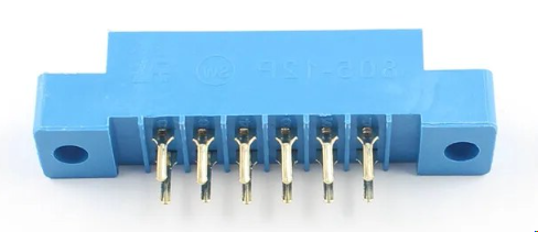 The Node Bus Hub is implemented on PCB containing at least one Card Edge Connector. Supported connectors are the 805 Type A (PTH), 12P (2x6), with a 3.96mm pin pitch. The Node Bus connections are connected to the connector’s 12 pins. Connecting multiple connectors serially provide power and communications support between multiple cards.
ESD Protection Diode
An ESD (Electrostatic Discharge) Protection Diode is used to protect electronic circuits from electrostatic discharge, which can cause damage to sensitive components. In the BOD Card, it protects the I2C lines from ESD events.
Fast Blow Fuse
A Fast Blow Fuse is a type of fuse that quickly opens (blows) when the current exceeds its rated value. It is designed to protect sensitive electronic circuits that could be damaged by even short periods of excessive current. Fast blow fuses are commonly used in devices where immediate protection is necessary, such as power supplies and motor controllers.
Ferrite Bead
A Ferrite Bead is a (inductive) passive electronic component used to suppress high-frequency noise in electronic circuits. Used by many of the cards on the I2C lines to reduce interference and ensure reliable communication.
Flyback Diode
A flyback diode is a diode placed across an inductive load, such as a relay or motor, to protect against voltage spikes generated when the current is suddenly interrupted. It allows the current to safely dissipate, preventing damage to other components.
FSR
An FSR (Force Sensitive Resistor) is a resistive sensor that decreases in resistance as force or pressure is applied to its sensing surface. These sensors typically respond to pressures ranging from a few grams to several kilograms, making them well suited for detecting light touch or object presence.
LCC Fusion uses FSRs with the Resistive Sensor Breakout Board to detect the presence of rolling stock or trains. When installed under track or mounting pads, FSRs can detect whether a train car is present by measuring the analog voltage generated via the LM358 op-amp and interpreting it through the ESP32 ADC on the Node Card. This allows LCC events to be triggered based on load detection without requiring IR or magnetic sensors.
Galvanic Isolation
Galvanic Isolation is a method of electrically separating two parts of a circuit to prevent direct current flow between them while still allowing signal or power transfer. Achieved through components like transformers, optocouplers, or capacitors, it protects sensitive circuits from electrical noise, surges, and ground loops by blocking conductive paths, ensuring safe and reliable operation across connected systems.
GPIO Expander
A GPIO Expander is a device that increases the number of General Purpose Input/Output (GPIO) pins available to a microcontroller. The MCP23017, used in the BLVD Card, serves as a GPIO expander, enabling it to monitor multiple track blocks.
Common Ground
A Common Ground is the shared 0 V electrical reference used by all logic, power, and devices in the system.
For LCC Fusion, the common ground is provided by the Node Card and CAN-Power Card, and shared with other cards through the Node Bus Hub. Optionally, this ground can be extended to breakout boards via the card’s LINE 8 selector or through the layout DC accessory bus (if its negative rail is bonded to the Node’s ground).
NOTE: If two different power supplies are used (for example, one for powering LCC Fusion cards/hub and a second power supply for the layout accessory bus), their DC negative outputs must be tied together so devices and signals share the same reference. Never tie the AC input sides together — only the DC output grounds.
Rule of Thumb: All signals and devices must share one common ground for reliable operation.
I2C Bus
A communication protocol used for connecting and configuring devices within the LCC Node cluster, allowing multiple cards to communicate.
I2C
I2C (Inter-Integrated Circuit) is a communication protocol that allows multiple devices (such as microcontrollers and peripherals) to communicate with each other over a two-wire bus. In the context of the LCC Fusion project, I2C is used for communication between different cards, such as the Audio Card and Node Card, enabling them to exchange data like text messages and control signals.
I2S
I2S (Inter-IC Sound) is a serial bus interface standard used for connecting digital audio devices. It allows the transmission of audio data between components such as microcontrollers, digital-to-analog converters (DACs), and audio amplifiers. In the LCC Fusion project, I2S is used to transmit audio signals from the ESP32 to the audio amplifier, ensuring high-quality audio playback.
Jumper
A small connector used to close, open, or bypass electrical circuits on the Output Card, used for configuring voltage and communication settings.
LDR
An LDR (Light Dependent Resistor) is a passive two-wire resistive sensor that changes its resistance based on the amount of incident light. Resistance decreases as light intensity increases, typically ranging from tens of kilohms in dim light to under 1 kΩ in bright light.
LCC Fusion uses LDRs with the Resistive Sensor Breakout Board to detect changes in room or layout lighting. The LDR is connected as part of an analog sensing channel and monitored through the LM358 op-amp and ESP32 ADC on the Node Card. This enables automated responses to ambient light levels, such as activating building lights or triggering day/night transitions.
Li-Po
A Li-Po Battery refers to a lithium polymer battery pack configured in a series arrangement with three cells, resulting in a nominal voltage of 11.1 V and a maximum fully charged voltage of 12.6 V. This battery configuration is commonly used in portable electronic devices for providing a stable, high-capacity power source.
MCP23017
The MCP23017 is a 16-bit I/O expander with I2C interface, allowing for additional input/output pins in microcontroller-based systems. It is used in the many of the LCC Fusion Project cards to interface with an Node Card via the Node Bus Hub.
Network Cable
A network cable, commonly known as an Ethernet cable, is a physical medium used to connect devices within a network, facilitating the transmission of data between computers, routers, switches, and other networked devices. These cables typically consist of twisted pairs of copper wires and use RJ45 connectors for wired connections in local area networks (LANs).
Recommendation: For applications requiring higher data rates and power transmission, CAT6 cables are recommended. CAT6 cables can carry more current with less voltage drop compared to older standards, and their increased stiffness makes them more durable and easier to insert into connectors, ensuring a more reliable connection.
Optocoupler
An Optocoupler is an electronic component that transfers electrical signals between two isolated circuits using light. It provides electrical isolation, protecting sensitive components from high voltages and noise. In the BOD Card, the optocoupler isolates the track voltage from the MCP23017 GPIO pins.
Polyfuse
A Polyfuse is a resettable fuse that protects circuits from overcurrent conditions. When the current exceeds the fuse’s rated limit, the Polyfuse increases in resistance and limits the current flow, typically resetting once the current returns to safe levels. Common current ratings range from 250 mA to several amps depending on the model used.
Pull-up
A Pull-up Resistor is used in electronic circuits to ensure a terminal is at a high (logic 1) level when it is not actively driven. In the BLVD Card, pull-up resistors are used to ensure the MCP23017 GPIO pins have a defined logic level.
PWM
Pulse Width Modulation (PWM) is a versatile technique for controlling the power delivered to an electronic load by varying the width of pulses in a pulse train. In model railroad automation, PWM is commonly used to control motor speeds, adjust LED brightness, and manage other devices requiring precise variable power. By modifying the duty cycle (the ratio of the pulse width to the total period), PWM enables fine-tuned control of power delivery, making it an indispensable tool for optimizing performance in the LCC Fusion project.
One of the most practical applications of PWM in the LCC Fusion project is controlling LED brightness. By adjusting the duty cycle, PWM not only changes the light intensity but also creates different lighting effects that simulate a variety of environments.
LED Brightness Control
The brightness percentage determines the intensity of light emitted by the LED. Although the LED is fixed at a cool white color temperature (5000K–7000K), adjusting the brightness can influence the perceived lighting effect, creating different moods and functionality:
- Low Brightness (0%–40%): Produces a softer, more ambient light, evoking the warmth of early morning or evening lighting.
- Medium Brightness (40%–70%): Offers a balanced, daylight-like illumination, ideal for general-purpose use.
- High Brightness (70%–100%): Delivers bright, cool light, resembling midday sunlight, perfect for task-oriented or high-visibility applications.
Shield
In the context of an ESP32, a shield is an additional hardware board or module that can be connected to the ESP32 development board to expand its functionality. Shields are designed to be stackable, allowing multiple shields to be used together, depending on the specific requirements of the project. They typically connect to the ESP32 through its GPIO (General Purpose Input/Output) pins and may include components like sensors, actuators, communication modules, or power management circuits. Shields simplify the process of adding new capabilities to the ESP32 by providing pre-built, plug-and-play hardware that interfaces seamlessly with the main board.
Shunt
A shunt resistor is a precision, low-resistance component placed in series with a load to measure current flow. As current passes through the shunt, it creates a small voltage drop that is directly proportional to the current according to Ohm’s law (V = IR). By measuring this voltage differential with an ADC like the ADS1115, the current in the circuit can be accurately calculated. Additionally, by comparing the voltage before and after the shunt, you can also determine the overall voltage drop caused by the load, helping to assess any losses or drops in the supply voltage due to the load’s resistance.
Stencil
In PCB manufacturing and assembly, a Stencil is a thin sheet of material, usually made from stainless steel or polyimide, that is used to apply solder paste to specific areas of the PCB. The stencil has cutouts corresponding to the pads where components will be placed. During the assembly process, the stencil is aligned with the PCB, and solder paste is spread across the stencil, filling the cutouts. When the stencil is removed, the solder paste remains on the designated pads, ready for component placement. Proper use of a stencil ensures that the solder paste is applied accurately, which is critical for reliable solder joints and overall PCB performance.
Supermini
The Supermini ESP32-S3 Development Board is a compact, high-performance microcontroller board based on the ESP32-S3 chip, which features dual-core processors with Wi-Fi and Bluetooth LE connectivity. Designed for space-constrained projects, this development board offers a rich set of peripherals, including GPIOs, I2C, SPI, UART, and ADC interfaces, making it ideal for IoT, embedded systems, and wireless communication applications. Its low power consumption and small form factor make it a versatile solution for developing smart devices with advanced wireless capabilities.
TVS Diode
A TVS (Transient Voltage Suppression) Diode is a protective component that clamps voltage spikes to prevent damage to electronic circuits. In the BLVD Card, TVS diodes are used to protect the circuit from high-voltage transients that could occur on the track.
Voltage Glitch
A brief, unintended spike or drop in voltage within an electronic circuit that can disrupt normal operations or potentially damage sensitive components. The LCC Fusion Project safeguards against voltage glitches by implementing multiple protective measures:
- TVS (Transient Voltage Suppression) Diodes: Clamp voltage spikes to prevent them from reaching and damaging sensitive components.
- Optocouplers: Provide electrical isolation between different sections of the circuit, blocking high-voltage transients from propagating.
- Polyfuses (Resettable Fuses): Limit overcurrent conditions by increasing resistance when excessive current flows, protecting against potential short circuits.
- Ferrite Beads: Suppress high-frequency noise on power and signal lines, reducing the likelihood of voltage fluctuations caused by electromagnetic interference.
- ESD (Electrostatic Discharge) Protection: Utilize ESD protection diodes and components to guard against static electricity buildup and discharge that can damage ICs.
- Flyback Diodes: Protect against voltage spikes generated when switching inductive loads (like motors and relays) by providing a path for the induced current.
- Decoupling Capacitors: Stabilize power supply lines and filter out noise, ensuring that ICs receive a clean and steady voltage supply.
Voltage Divider
A voltage divider is used to scale down the input voltage to a safe level for use by IC’s such as the ADS1115 IC. Below are examples used by the Power-CAN Card for use with an ADS1115 IC measuring higher voltages.
-
For a 40 V input, a resistor network with R1 = 47kΩ and R2 = 8.2kΩ scales 40 V to approximately 5.94 V.
-
For a 12 V input, using equal resistor values (R1 = 10kΩ and R2 = 10kΩ) scales the voltage down to 6V.
This is calculated using the formula:
\[V_{out} = V_{in} \times \frac{R2}{R1 + R2}\]Zener Diode
A Zener diode is a type of diode designed to allow current to flow in the reverse direction when the voltage exceeds a specific breakdown voltage, known as the Zener voltage. Common Zener voltages range from 3.3 V to 12 V, and they are used in voltage regulation and protection circuits.
Electrical Components
6N137 {#6n137}
The 6N137 is a high-speed optocoupler with a transistor output. It provides electrical isolation between two circuits while transmitting digital signals at speeds up to 10Mbps.
In the LCC Fusion Project, it’s used to isolate the CAN Bus from the Node’s internal electronics, protecting the system from voltage spikes and ground-loop noise.
74HC00 {#74hc00}
The 74HC00 is a quad 2-input NAND gate IC. It operates from a supply voltage range of 2 V to 6V, making it suitable for a wide range of logic-level applications. Each gate in the IC performs the NAND operation, outputting LOW only when both inputs are HIGH.
74HC4051D {#74HC4051D}
The 74HC4051D is an 8-channel signal switch that lets one input or output line connect to any of eight sensor lines. In the LCC Fusion Project, it’s used on the Node Analog Sensor Breakout Board so a single Node Card can read several analog sensors by switching between them electronically.
74HCT14D {#74hct14d}
The 74HCT14D is a signal conditioning chip that cleans up noisy or unstable input signals by converting them into sharp, reliable digital signals. In the LCC Fusion Project, it’s used to stabilize inputs from sensors or switches before they’re read by the Node Card or other logic circuits.
ACS712
The ACS712 is a current sensor IC that provides an accurate current measurement based on the Hall effect. In the LCC Fusion Project, it’s used to monitor current from the track and voltage regulators.
ADS1115 ADC
The ADS1115 is a 16-bit analog-to-digital converter (ADC) featuring a programmable gain amplifier (PGA) and an I²C interface. It supports both single-ended and differential input configurations—allowing for precise voltage and current measurements (e.g., across a shunt resistor).
In the LCC Fusion Project, it’s used by the Power-CAN Card to monitor the voltage and current of the power supply input and the regulated output to the Node Bus Hub.
AT24C02
The AT24C02 is a small memory chip that keeps up to 256 bytes of information even when power is turned off. In the LCC Fusion Project, it’s used to store a card’s identification and description. It connects to the Node Card using the same I²C communication lines shared by other cards. It is programmed via the Node Card serial monitor by entering P.
BLM31
The BLM31 is a ferrite bead used to reduce electrical noise and keep signals stable. In the LCC Fusion Project, it helps filter out interference on power and communication lines—such as the I²C and CAN Bus—to ensure reliable data flow between connected cards.
BSS138
The BSS138 is an N-channel MOSFET used for low-power switching applications. It operates with a maximum drain-source voltage of 50 V and can handle up to 200 mA of continuous drain current. In the LCC Fusion Project, it’s commonly used to drive relays, control outputs, or shift logic levels between different voltage sections, allowing the Node Card to safely interface with other devices.
GL5528
The GL5528 is a light-dependent resistor (LDR) that changes resistance based on light levels. In the LCC Fusion Project, it’s used with sensor cards to detect ambient light—for example, to sense when a train passes over a section of track or when lighting conditions change on the layout.
IRLML6402 MOSFET
The IRLML6402 is a P-channel logic-level MOSFET. It has a maximum drain-source voltage of 20 V and can handle up to 3.7A of continuous drain current. In the LCC Fusion Project, it’s commonly used to control or disconnect power on 3.3 V and 5 V lines, allowing the Node Card to safely manage power to sensors, LEDs, or other modules.
IRLZ44N
The IRLZ44N is an N-channel logic-level MOSFET. It can handle a maximum drain-source voltage of 55 V and a continuous drain current of 47A. In the LCC Fusion Project, it’s typically used to drive motors, solenoids, or high-power lighting directly from logic-level control signals provided by the Node or Output Cards.
KBL406
The KBL406 is a bridge rectifier used for converting AC input into DC output. It can handle up to 600 V reverse voltage and provides a maximum forward current of 4A. In the LCC Fusion Project, it’s used on boards like the Servo Breakout Board to let users connect either AC or DC power sources safely, ensuring the correct polarity and providing a steady DC supply for regulators and connected devices.
LM7805CV
The LM7805CV is a 5 V linear voltage regulator that provides a steady 5 V output for powering electronic circuits. In the LCC Fusion Project, it’s used on boards that need a simple and reliable 5 V source for logic and sensor power. While less efficient than switching regulators, it’s valued for its ease of use, built-in protection features, and stable output for low-current applications.
L7812CV
The L7812CV is a 12 V linear voltage regulator that provides a steady 12 V output for powering electronic circuits. In the LCC Fusion Project, it’s used on boards such as the Node Card to supply clean, regulated power to the Node Bus or other connected cards. It’s valued for its simple design, built-in overload and thermal protection, and reliable performance in moderate-current applications.
LM1117-3V3
The LM1117-3V3 is a 3.3 V linear voltage regulator that provides a stable output for low-voltage circuits. In the LCC Fusion Project, it’s used to power 3.3 V components such as ESP32 microcontrollers and I²C devices, ensuring clean and reliable operation across the Node and peripheral cards.
LM2596S-ADJ
The LM2596S-ADJ is an adjustable switching voltage regulator that allows the output voltage to be set using external resistors. In the LCC Fusion Project, it can be configured to provide either 5 V or 12 V output by connecting a 4.7 kΩ or 10 kΩ resistor, respectively. This flexibility makes it ideal for powering different circuit sections without changing regulators. It offers high efficiency and supports higher current loads, provided that proper filtering capacitors are used for stable operation.
LM393
The LM393 is a dual voltage comparator used to detect voltage differences between two inputs and provide a digital HIGH or LOW output. In the LCC Fusion Project, it’s used in voltage sensing circuits—such as detecting low voltage levels or short conditions—helping trigger logic events or protect connected devices.
LM358
The LM358 is a dual operational amplifier (op-amp) designed for single-supply operation, ideal for reading small analog signals in 3.3 V or 5 V systems. In the LCC Fusion Project, it’s used on the Resistive Sensor Breakout Board to amplify signals from photoresistors (LDRs), force sensors (FSRs), and pressure sensors. The op-amp outputs a clean analog voltage (0–3.3 V) that the ESP32 ADC on the Node Card reads to generate LCC events based on light, touch, or resistance changes.
M54562FP
The M54562FP is an 8-channel Darlington transistor array capable of sinking up to 500 mA per channel at voltages up to 50 V. Each channel includes built-in clamping diodes for protection against inductive loads. In the LCC Fusion Project, it’s used to drive higher-current devices such as LEDs, relays, and motors from logic-level control signals.
MAX98257A
The MAX98257A is a Class D audio amplifier that can deliver up to 3.2 W into an 8 Ω speaker with a 2.5 V – 5.5 V supply. In the LCC Fusion Project, it’s used on the Audio Card to provide clear, efficient audio output for alerts, messages, or sound effects.
MB6S
The MB6S is a bridge rectifier used to convert AC input to DC output. It supports up to 600 V reverse voltage and 0.5 A forward current. In the LCC Fusion Project, it’s found on power-input sections to rectify accessory bus AC into DC for the board’s voltage regulators.
MCT6H
The MCT6H is an optocoupler that isolates control signals between high-voltage and low-voltage sections of a circuit. It handles input currents up to 60 mA and output voltages up to 30 V. In the LCC Fusion Project, it’s used to protect logic circuits when switching external devices or when electrical isolation is required.
MCP23017
The MCP23017 is a 16-bit I/O expander that communicates over the I²C bus, adding up to 16 extra digital input/output lines to a microcontroller. In the LCC Fusion Project, it’s used across multiple cards to extend the Node’s GPIO capacity, enabling control of sensors, buttons, and LEDs through I²C communication.
MCP7383T
The MCP7383T is a Li-ion/Li-polymer battery charging controller supporting input voltages from 4.5 V – 12 V and programmable charge currents up to 1 A. In the LCC Fusion Project, it’s used on the Battery Card to safely charge and manage backup batteries for uninterrupted Node power.
MFRC523
The MFRC523 is an NFC/RFID controller operating at 13.56 MHz, supporting MIFARE and other contactless protocols via SPI, I²C, or UART. In the LCC Fusion Project, it’s used on the NFC Reader Card to read and write RFID tags, supporting identification and control features within the LCC network.
NE556
The NE556 is a dual-timer IC that combines two independent 555 timers in one 14-pin package. Each timer can operate in monostable (one-shot) or astable (oscillator) mode for generating pulses, delays, or frequencies. In the LCC Fusion Project, it’s used on timing circuits such as servo and turnout controllers, providing precise pulse width and timing control without needing a microcontroller.
PCA9515A
The PCA9515A is a bi-directional I²C repeater used to isolate and extend I²C bus segments. It buffers signals between two sides of the bus, reducing capacitance and improving reliability over long cables. In the LCC Fusion Project, it’s used on Node Bus Hubs to separate I²C segments, allowing stable communication and supporting automatic pull-up detection for each segment.
PCA9685
The PCA9685 is a 16-channel PWM driver that communicates via I²C and provides 12-bit resolution for precise control of servos, LEDs, and motors. It operates from 2.3 V to 5.5 V, making it compatible with both 3.3 V and 5 V systems. In the LCC Fusion Project, it’s used on the PWM Card to control servos and LED lighting, providing smooth and coordinated motion or brightness control across multiple channels.
PESD1CAN
The PESD1CAN is a transient voltage suppression (TVS) diode designed to protect communication lines such as CAN and I²C from electrostatic discharge (ESD) and voltage spikes. In the LCC Fusion Project, it’s used on Node Cards and I²C-based boards to safeguard signal integrity and protect connected ICs from electrical transients.
PT204
The PT204 is a phototransistor that detects light and converts it into an electrical signal. It can handle voltages up to 30 V and currents up to 20 mA. In the LCC Fusion Project, it’s used on optical detection boards such as the POD Card to sense trains or motion, enabling event generation based on light changes across the track.
RV24YN20S
The RV24YN20S is a 24 mm rotary potentiometer used for adjustable analog input. It provides a linear resistance taper (B104 = 100 kΩ), producing a variable voltage output based on its rotation angle. In the LCC Fusion Project, it’s used with the Resistive Sensor Breakout Board and LM358 op-amp to provide a user-adjustable voltage read by the ESP32 ADC on the Node Card—allowing control dials for speed, lighting, or signal thresholds.
SMAJ5A
The SMAJ5A is a transient voltage suppression (TVS) diode rated for a 5 V standoff voltage and 400 W peak pulse power. In the LCC Fusion Project, it’s used to protect low-voltage circuits (such as 5 V power rails and I²C lines) from voltage spikes and electrostatic discharge.
SMBJ18A
The SMBJ18A is a TVS diode with an 18 V standoff voltage and a 400 W pulse power rating. In the LCC Fusion Project, it’s typically used on power-input sections to protect the Node and Hub cards from high-voltage surges or transient spikes on the accessory bus.
SN65HVD233DR
The SN65HVD233DR is a 3.3 V CAN bus transceiver supporting data rates up to 1 Mbps. It provides differential transmit and receive functions for robust communication over long cables. In the LCC Fusion Project, it’s used on Node Cards to interface the ESP32 with the CAN network, enabling reliable LCC event messaging between devices.
SN74HCT14
The SN74HCT14 is a hex Schmitt-trigger inverter that converts noisy or slow signals into clean digital outputs. In the LCC Fusion Project, it’s used for signal conditioning and debouncing, ensuring that sensor or button inputs are read reliably even in electrically noisy environments.
SS310
The SS310 is a Schottky diode rated for 100 V reverse voltage and 3 A forward current. It features a low forward voltage drop and fast switching characteristics. In the LCC Fusion Project, it’s used for reverse-current and polarity protection on power lines, helping safeguard Node and peripheral cards during power transitions or wiring mistakes.
TB6612FNG
The TB6612FNG is a dual H-bridge motor driver capable of driving two DC motors or one stepper motor. It supports a motor supply voltage (VM) from 4.5 V – 13.5 V, delivering up to 1.2 A continuous (and 3.2 A peak) per channel. In the LCC Fusion Project, it’s used on the DC Motor Driver Breakout Board to efficiently control motors and other inductive loads with low heat generation.
TBD62083A
The TBD62083A is an 8-channel Darlington transistor driver that can sink up to 500 mA per channel at voltages up to 50 V. It includes built-in clamping diodes for inductive load protection. In the LCC Fusion Project, it’s used on the Output Card and PWM Card to safely drive LEDs, relays, and motors from logic-level control signals.
TC4428
The TC4428 is a dual MOSFET driver that can source or sink up to 1.5 A per channel with a supply voltage up to 18 V. It’s designed for high-speed switching and precise control of power MOSFETs. In the LCC Fusion Project, it’s used in motor control and power-switching circuits, ensuring fast, reliable gate drive for MOSFET-based outputs.
TQ2-L2-12V
The TQ2-L2-12V is a dual-coil latching relay with DPDT (double-pole, double-throw) contacts that hold their state after activation. It operates with a 12 V DC coil and is designed for reliable polarity or signal switching. In the LCC Fusion Project, it’s used by the Turnout Servo Switch Machine Breakout Board, Turnout Coil Switch Machine Breakout Board, and BRD Card to switch rail or frog polarity, such as in reversing loops.
TQ2-L-5V
The TQ2-L-5V is a DPDT latching relay with two changeover contacts and a 5 V DC coil. It’s compact and reliable for low-level signal switching. In the LCC Fusion Project, it’s used on the Relay Breakout Board to switch connected devices or track power under control of a Node or Output Card.
TQ2-5V
The TQ2-5V is a DPDT non-latching relay that operates with a 5 V DC coil. It provides two changeover contacts for dependable low-signal switching. In the LCC Fusion Project, it’s used on the Turnout Slow Motion Switch Machine Breakout Board to switch frog polarity for slow-motion turnout motors.